Hyundai Tucson: Differential Carrier Assembly - Removal
Components Location

- Rear differential carrier assembly
- Rear driveshaft assembly
- Coupling Assembly
- Propeller shaft assembly
Components

- Pinion lock nut
- Oil seal (pinion side)
- Pinion outer bearing
- Oil seal (case side)
- Packing
- Drain plug
- Differential carrier case
- Air breather
- Differential bearing shim (case side)
- Differential bearing shim (cover side)
- Differential carrier case side cover
- Oil seal (cover side)
- Filler plug
- Filler gasket
- Pinion bearing spacer
- Pinion inner bearing
- Pinion inner bearing adjust shim
- Pinion drive gear
- Differential gear bearing (case side)
- Ring gear
- Gear carrier
- Differential gear bearing (cover side)
Removal
- Disconnect the (-) battery terminal.
- Remove the rear driveshaft.
(Refer to Rear Driveshaft Assembly - "Rear Driveshaft")
- Remove the propeller shaft.
(Refer to Propeller Shaft Assembly - "Propeller Shaft")
- Remove the coupling assembly.
(Refer to All Wheel Drive (AWD) System - "Direct Electro Hydraulic Actuator Coupling")
- Install a jack oil the lower part of the differential.
- Remove the differential carrier assembly (A) after loosening the mounting bolts.
Tightening torque : 68.6 - 88.2 N m (7.0 - 9.0 kgf-m, 50.6 - 65.0 lb ft)


- Remove the differential carrier bracket (A) after loosening the mounting bolts

Inspection
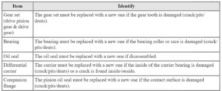
- After clearing, check for damage parts or abrasion. Follow the below method, if any are noticed.

- Check the tooth contact pattern.


WARNING
1) Tooth contact pattern is a method for judging the result of the adjustmentof drive pinion height and final drive gear backlash. The adjustment of drivepinion height and final drive gear backlash should be repeated until the toothcontact patterns are similar to the standard tooth contact pattern.
2) When you cannot obtain a correct pattern, the drive gear and drive pinionhave exceeded their limits.
Both gears should be replaced as a set.
Disassembly
READ NEXT:
 Differential gear assembly
Remove the drain plug packing (A) and drain plug (B) to drain the gear
oil.
Loosen the differential side cover mounting bolts.
Widen the gap between the side cover and the case to remove the side
cover (A).
Remo
 Pinion drive gear assembly
Fix the differential carrier assembly using the SST (09501-C9230,
0K530-P2500, 0K501-P2232).
Loosen the pinion gear lock nut using the SST (09501-C9230).
WARNING
When istalling lock nut, use a new one.
Remove the pinion dr
 Differential carrier case
Remove the pinion oil seal (A).
WARNING
When installing oil seal (A), replace oil seal with a new one.
Remove the outer pinion bearing (A).
WARNING
Do not reuse the removed bearing.
Remove the outer pinion bearing race (A)
SEE MORE:
 Handling Wires and Harnesses
Secure wires and wire harnesses to the frame with their respective wire
ties at the designated
locations.
Remove clips carefully; don't damage their locks (A).
Slip pliers (A) under the clip base and through the hole at an ang
 Connector assembly status test- Troubleshooting
Connector assembly status test
Disconnect the ignition coil connectors (A) and reinstall it.
Test for changing position of each ignition coil
Ignition coil w/ misfire code
Ignition coil w/o misfire code
WARNING
Do not move wi
Information
- Home
- Hyundai Tucson - Fourth generation (NX4) - (2020-2023) - Owner's Manual
- Hyundai Tucson - Fourth generation (NX4) - (2020-2023) - Workshop Manual