Hyundai Tucson: Heated Steering Wheel Control Module (Integrated Body Control Unit (IBU)
Hyundai Tucson - Fourth generation (NX4) - (2020-2023) - Workshop Manual / Steering System / Steering wheel / Heated Steering Wheel Control Module (Integrated Body Control Unit (IBU)
- Turn the ignition switch OFF and disconnect the battery negative (-) cable.
- Remove the glove box.
(Refer to Body - "Glove Box")
- Remove the heater control unit.
(Refer to Heating,Ventilation And Air Conditioning - "Heater Control Unit")
- Remove the IBU (A) after loosening the mounting bolts and nuts.
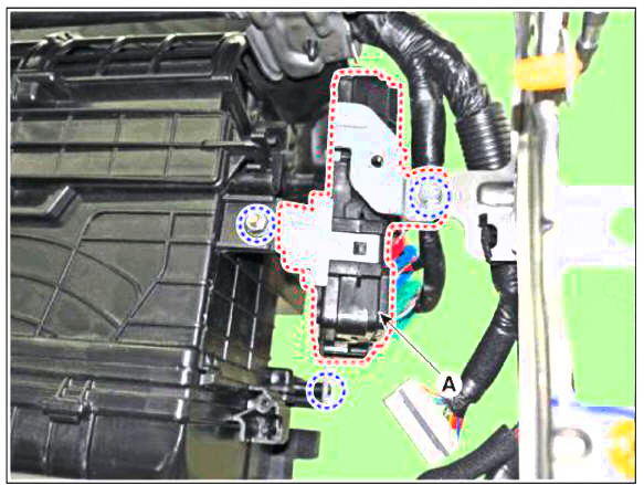
- Remove the IBU (A) after disconnecting the connector

Inpection
- Measure the resistance of NTC and Heated pad.
NTC resistance - 10.0 k +- 5 %
(25ºC)
Heated pad resistance - 1.90  +-
10 %
- Measure the temperature.
- The temperature of wheel surface must rise from -20ºC to 20ºC in 6 minutes.
- The temperature of wheel surface must reach 38ºC +- 4 0 C in 25 minutes.

Schematic Diagrams
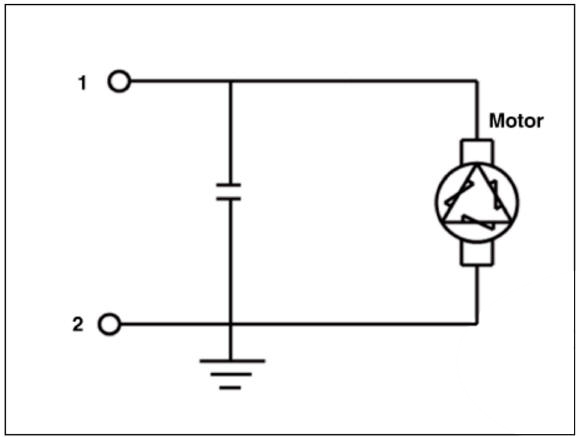

Removal
- Remove the steering wheel.
(Refer to Steering Wheel - "Removal")
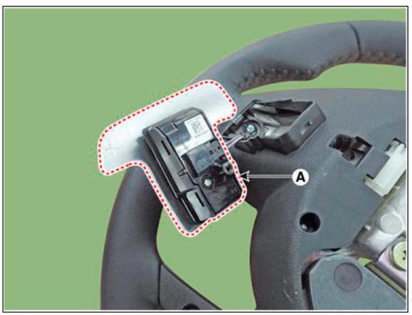
- Loosen the paddle shift switch mounting screw (A).
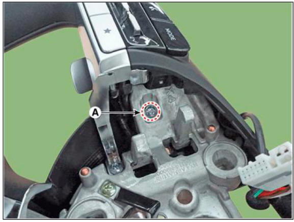
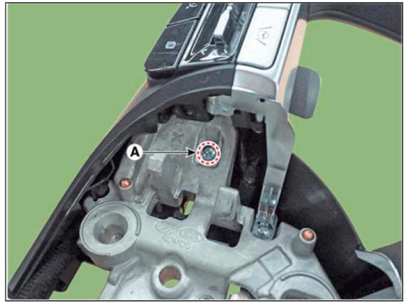
- Remove the paddle shift switch (A) after disconnecting the connector

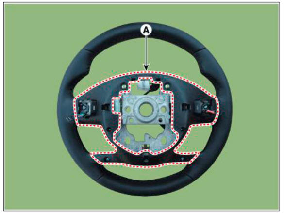
- Remove the lower cover (A) after loosening the screw.
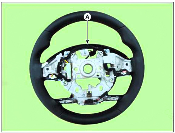
- Disconnect the wiring (A).
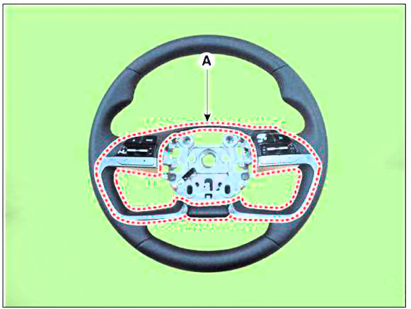
- Remove the steering wheel bezel (A).
- Remove the haptic motor (A) after loosening the screws.

Installation
- To install, reverse the removal procedures.
READ NEXT:
 Motor Driven Power Steering - Description
Description
MDPS (Motor Dirven Power Steering) system uses an electric motor to assist
the steering force and it
is an engine operation independent steering system.
MDPS control module controls the motor operation according to information
re
 Column & Housing Noise Repair Guide
R-MDPS Warning lamp Diagnosis Guide
Inspection Items per DTC
Checking Connectors and Wiring
Checking Connectors and Wiring.
Check for damage, push-back, or improper connection in each connector and
wiring.
(1) Check th
SEE MORE:
 General Information
Description
System Description
Advanced Driver Assistance System (ADAS) analyzes the exterior environment of
a vehicle and driver status to provide
visibility / display / guide / warning for driving and parking.
System Configuration
Sp
 Parking Brake Pedal Stroke
Adjustment
WARNING
After disassembling/assembling the caliper body or replacing the
caliper, parking brake cable or brake
disc, re-adjust the parking brake.
To fit the cable, follow one of these procedures.
Apply a parking brake fully
Information
- Home
- Hyundai Tucson - Fourth generation (NX4) - (2020-2023) - Owner's Manual
- Hyundai Tucson - Fourth generation (NX4) - (2020-2023) - Workshop Manual