Hyundai Tucson: Crash pad center panel
Hyundai Tucson - Fourth generation (NX4) - (2020-2023) - Workshop Manual / Body (Interior and Exterior) / Crash Pad / Crash pad center panel
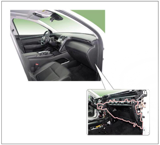
Component Location

- Crash pad center panel
Replacement
WARNING
- When piying with a flat-tip screwdriver, wrap it with protective tape, and apply protective tape around the related parts, to prevent damage.
- Put on gloves to protect your hands.
WARNING
Take care not to bend or scratch the trim and panels.
- Remove the floor console assembly.
(Refer to Floor Console - "Floor Console Assembly")
- Remove the crash pad under cover.
(Refer to Crash Pad - "Crash Pad Under Cover")
- Remove the glove box.
(Refer to Crash Pad - "Glove Box")
- Remove the front monitor.
(Refer to Body Electrical System - "Front Monitor")
- Remove the crash pad lower panel.
(Refer to Crash Pad - "Crash Pad Lower Panel")
- Remove the crash pad garnishRH.
(Refer to Crash Pad - "Crash Pad Garnish")
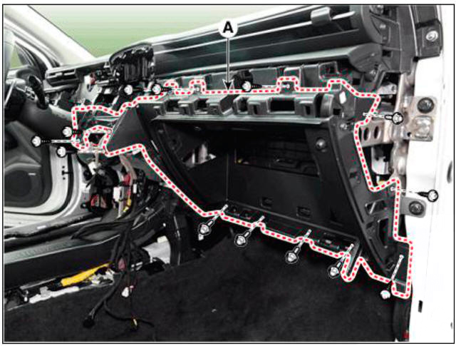
- Loosen the mounting screws, bolts and nuts, remove the crash pad center panel (A).

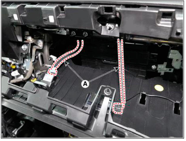
- Disconnect the connectors (A).

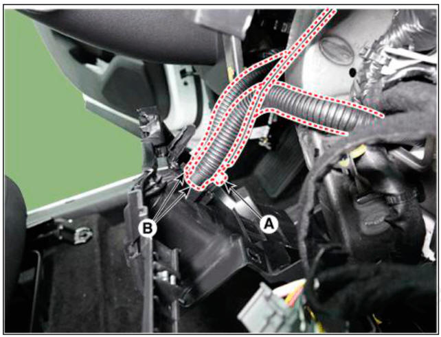
- Disconnect the in-car sensor connector (A) and hoses (B).

- To install, reverse removal procedure.
WARNING
- Make sure the connector are connected in properly.
- Replace any damaged clips.
READ NEXT:
 Main crash pad assembly
Component Location
Main crash pad assembly
Replacement
WARNING
When removing with a flat-tip screwdriver or remover, wrap
protective tape around the tools to prevent damage to
components.
Put on gloves to prevent hand injuries.
 Cowl cross bar assembly
Component Location
Cowl cross bar assembly
Replacement
WARNING
When removing with a flat-tip screwdriver or remover, wrap
protective tape around the tools to prevent damage to
components.
Put on gloves to prevent hand injuries.
SEE MORE:
 System operation
Front camera operating speed by each system :
The operating conditions of the front camera are as follows when the USM of
the following system is ON and the required operating speed is satisfied.
FCA, Forward Collision-Avoidance Assist
 Forward Collision-Avoidance
Assist Malfunction and
Limitations
Forward Collision-Avoidance Assist malfunction
When Forward Collision-Avoidance
Assist is not working properly, the 'Check
Forward Safety system (s)' warning
message will appear, and the and
warning lights will illuminate on the
cluster.
Information
- Home
- Hyundai Tucson - Fourth generation (NX4) - (2020-2023) - Owner's Manual
- Hyundai Tucson - Fourth generation (NX4) - (2020-2023) - Workshop Manual