Hyundai Tucson: Cowl cross bar assembly
Hyundai Tucson - Fourth generation (NX4) - (2020-2023) - Workshop Manual / Body (Interior and Exterior) / Crash Pad / Cowl cross bar assembly
Component Location
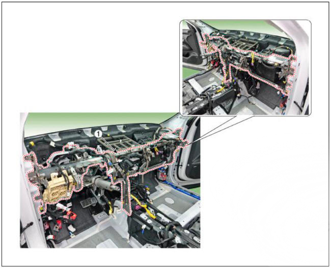
- Cowl cross bar assembly
Replacement
WARNING
- When removing with a flat-tip screwdriver or remover, wrap protective tape around the tools to prevent damage to components.
- Put on gloves to prevent hand injuries.
WARNING
Take care not to bend or scratch the trim and panels.
- Disconnect the negative (-) battery terminal.
- Remove the cowl top cover.
(Refer to "Cowl Top Cover")
- Remove the front wiper motor.
(Refer to Body Electrical System - "Front Wiper Motor")
- Loosen the engine room cowl cross bar assembly mounting bolts (A).
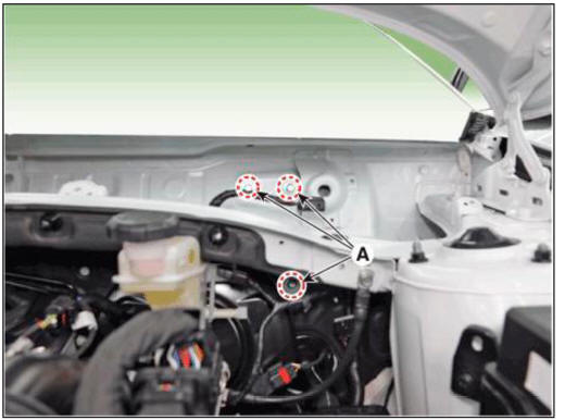
- Loosen the mounting nuts and through bolts in the frontal area and lower
the steering column.
(Refer to Steering System - "Steering Column and Shaft")
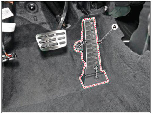
- Loosen the mounting bolt and nut, remove the accelerator pedal module (A).
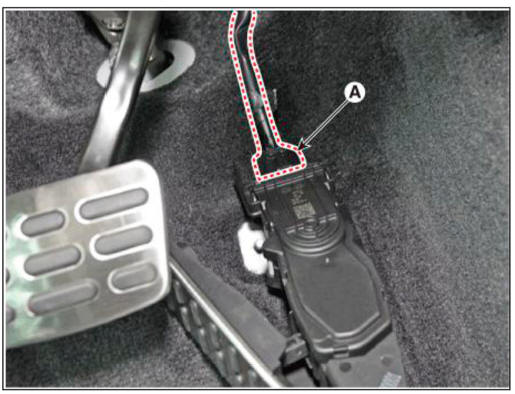
- Disconnect the accelator pedal connector (A)
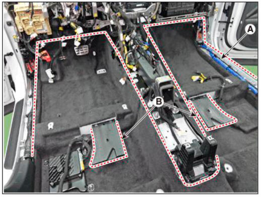
- Remove the rear air duct (B) and then separate the floor carpet (A) backwards.
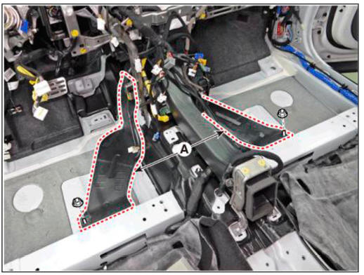
- Loosen the mounting nuts and remove the rear heating duct (A).
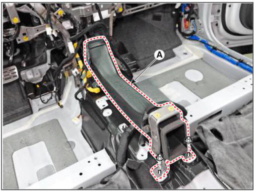
- Loosen the mounting nuts and remove the floor air duct (A).
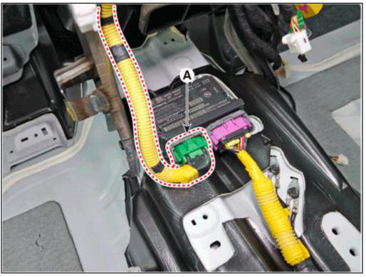
- Disconnect the airbag control module(SRSCM) connector (A).
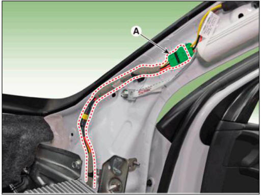
- Disconnect the connector (A) and the mounting wiring fasteners in the front pillar.
LH

RH
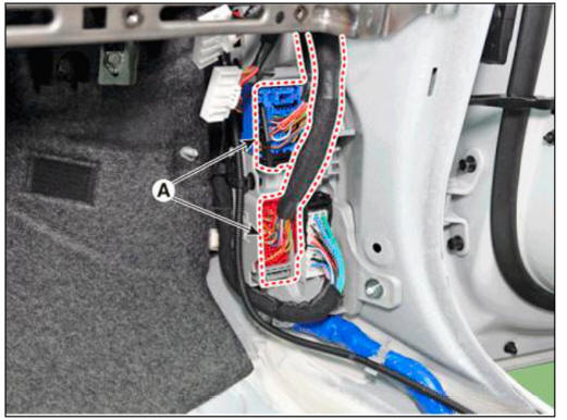
- Disconnect the multi box connectors (A).
LH

RH
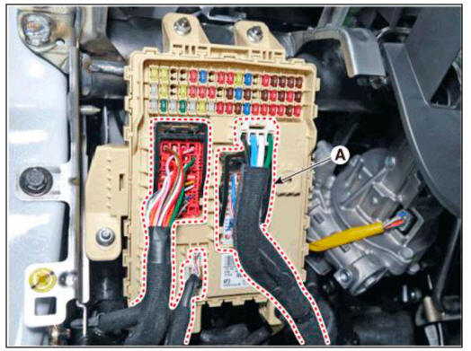
- Disconnect the passenger compartment junction box connectors (A).
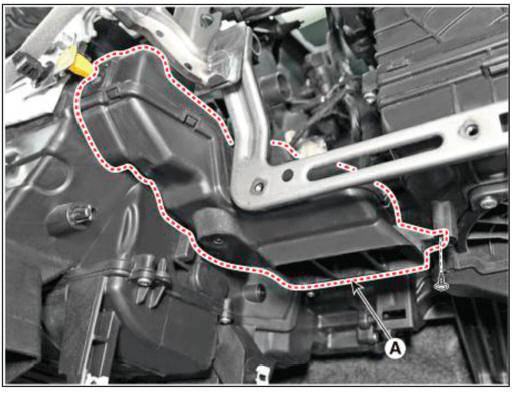
- Remove the shower duct.
LH
- Loosen the mounting screw, remove the shower duct (A).

- Disconnect the PM sesnor connector (A) and hose (B).

RH
- Loosen the mounting screw, remove the shower duct (A).
- Disconnect the heater and blower unit connectors.
- Disconnect the PTC heater connector (A).
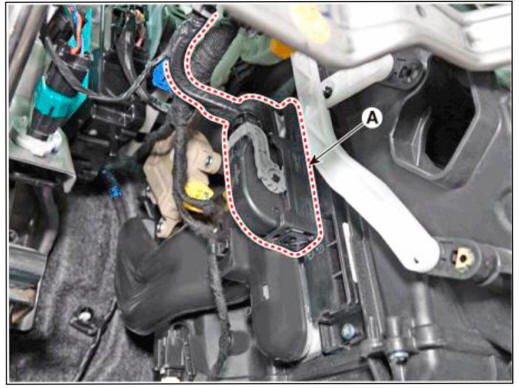
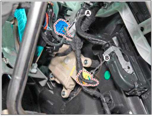
- Disconnect the driver's temperature control actuator connector (A) and mode control actuator connector (B).
- Disconnect the evaporator sensor connector (A).
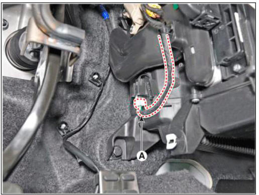
- Disconnect the auto defogging actuator connector (A).

- Disconnect the passenger's temperatur actuator connector (A) and power mosfet connector (B).
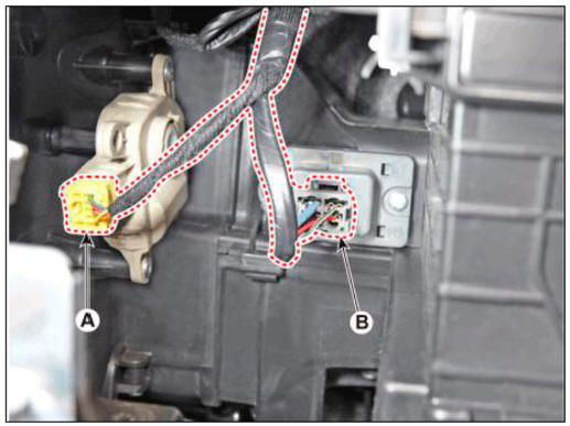
- Disconnect the intake actuator connector (A).
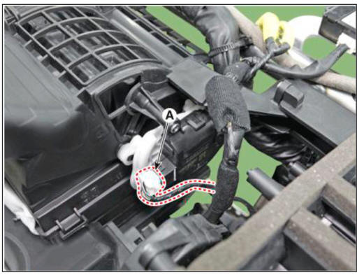
- Disconnect the blower motor connector (A).
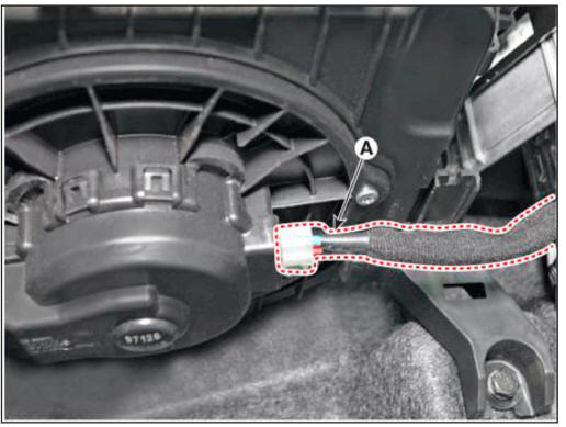
- Disconnect the heater control unit connectors (A).
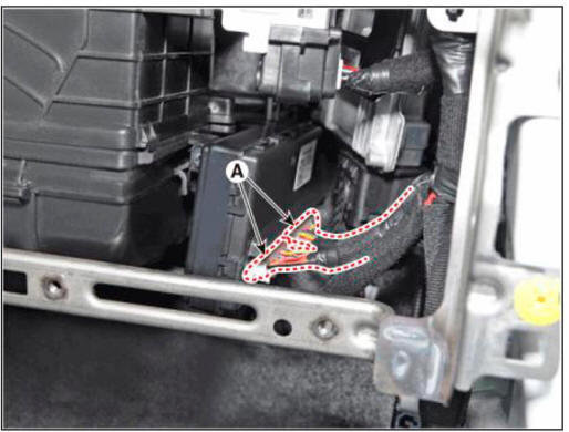
- Remove the integrated body control unit(IBU).
(Refer to Body Electrical System - "Integrated Body Control Unit (IBU)")
- Loosening the cowl cross bar side mounting bolt (B) after loosening the plug hole (A).
Tightening torque : 16.7 - 25.5 N.m (1.7 - 2.6 kgf.m, 12.3 - 18.8 lb-ft)
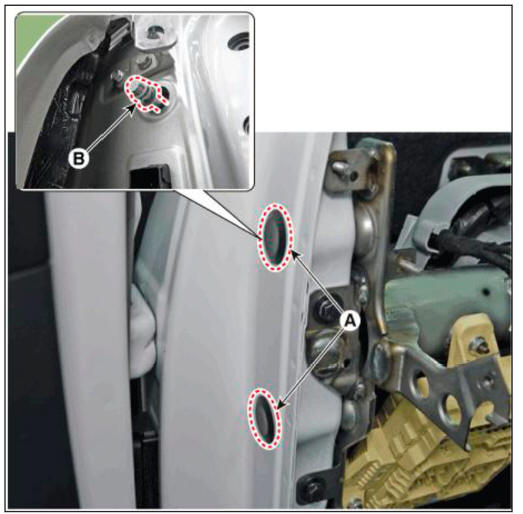
- Loosen the mounting bolts and remove the cowl croos bar assembly (A).
Tightening torque : 16.7 - 25.5 N.m (1.7 - 2.6 kgf.m, 12.3 - 18.8 lb-ft)
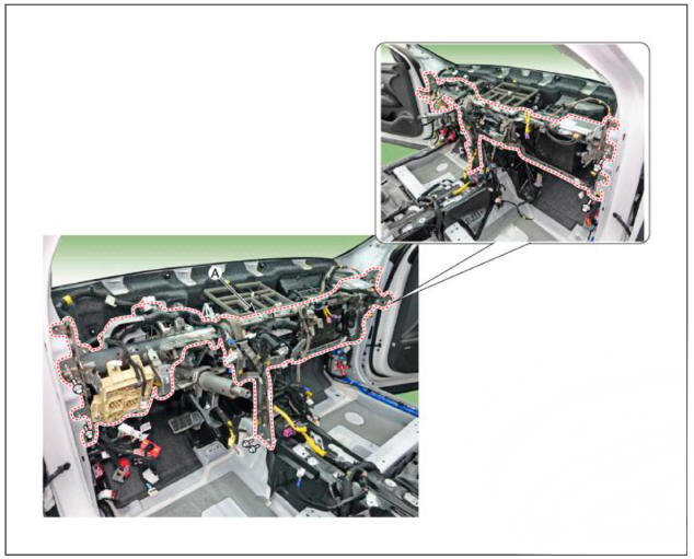
- To install, reverse removal procedure.
WARNING
- Make sure the crash pad fits onto the guide pins correctly.
- Before tightening the bolts, make sure the crash pad wire harnesses are not pinched.
- Make sure the connectors are plugged in properly, and the antenna lead is connected properly.
- Enter the anti- theft code for the radio, then enter the customer's radio station presets.
- Make sure that each of the assembly components operates properly.
- Replace any damaged clips (or pin-type retainers).
READ NEXT:
 Roof Trim - General type
Components
General type
Sunvisor LH
Sunvisor RH
Roof trim
Panorama sunroof type
Sunvisor LH
Sunvisor RH
Roof trim
Component Location
Sunvisor
Retainer
Replacement
Sunvisor
Remove the sunvisor pivot cov
 Roof trim assembly
Component Location
Roof trim assembly
Replacement
WARNING
When removing with a flat-tip screwdriver or remover, wrap
protective tape around the tools to
prevent damage to components.
Put on gloves to prevent hand injuries.
W
SEE MORE:
 Multifunction Switch Inspection
Check for continuity between the terminals in each switch position as
shown below.
Inspection (With Diagnostic Tool)
In the body electrical system, failure can be quickly diagnosed by using
the vehicle diagnostic system (d
 Windshield Wiper Washer - Removal
Disconnect the negative (-) battery terminal.
If necessary, release the wiper blade fixing clip(A) by pulling up and
remove the wiper blade(B) from the inside radius of
wiper arm.
Remove the cowl top cover.
(Refer to Body - &quo
Information
- Home
- Hyundai Tucson - Fourth generation (NX4) - (2020-2023) - Owner's Manual
- Hyundai Tucson - Fourth generation (NX4) - (2020-2023) - Workshop Manual