Hyundai Tucson: Wiring Precautions
SRS wiring can be identified by special yellow outer covering Observe the instructions described in this section.
- Never attempt to modify, splice, or repair SRS wiring. If there is an open or damage in SRS wiring, replace the harness.

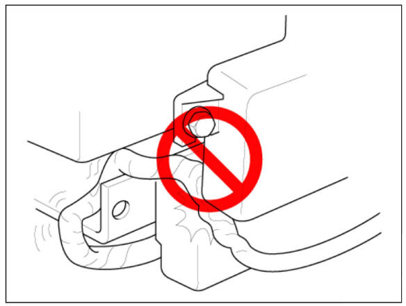
- Be sure to install the harness wires so that they are not pinched, or interfere with other parts.

- Make sure all SRS ground locations are clean, and grounds are securely fastened for optimum metal-to-metal contact. Poor grounding can cause intermittent problems that are difficult to diagnose.
Precautions for Electrical Inspections
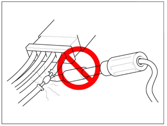
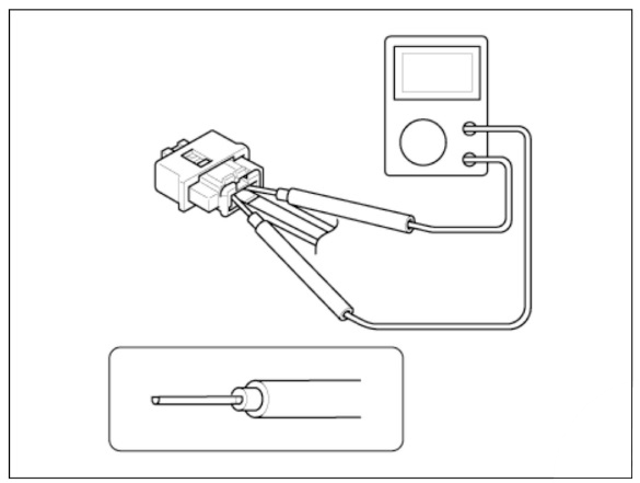
- When using electrical test equipment, insert the probe of the tester
into the wire side of the
connector.
Do not insert the probe of the tester into the terminal side of the connector, and do not tamper with the connector.

- Use a u-shaped probe. Do not insert the probe forcibly.
- Use specified service connectors for troubleshooting.
Using improper tools could cause an error in inspection due to poor metal contact.
Spring-loaded Lock Connector
Some SRS system connectors have a spring-loaded lock.
Airbag Connector
Disconnecting
To release the lock, pull the spring-loaded sleeve (A) and the slider (B), while holding the opposite half of the connector.
Pull the connector halves apart. Be sure to pull on the sleeve and not on the connector half.

Connecting
Hold both connector halves and press firmly until the projection(C) of the sleeve-side connector clicks to lock.

READ NEXT:
 Warning Lamp
Activation
Warning Lamp Behavior after Ignition On
As soon as the operating voltage is applied to the SRSCM ignition input, the
SRSCM activates the
warning lamp for a LED lamp check.
The lamp shall turn on for 6 seconds during the initialization phase an
 SRSCM
SRSCM
Components Location
Supplemental Restraint System Control Module (SRSC'M)
Gravity Side Impact Sensor (G-SIS) _ C pillar
Gravity Side Impact Sensor (G-SIS) _ B pillar
Front Impact Sensor (FIS) RH
Front Impact Sensor (FIS) LH
Pres
 Supplemental Restraint System Control Module (SRSCM)
Components Location
Supplemental Restraint System Control Module (SRSCM)
Supplemental Restraint System Control Module (SRSCM)
Removal
Disconnect the battery negative terminal.
WARNING
After disconnecting the cables
SEE MORE:
 Snow or icy conditions
The severe weather conditions of winter
quickly wear out tires and cause other
problems. To minimize winter driving
problems, you should take the following
suggestions:
You need to keep sufficient distance
between your vehicle and the vehicle i
 Rear Brake Caliper
Components
EPB Actuator
Caliper body
Caliper carrier
Pad retainer
Brake pad
Removal
Before removing the rear caliper, perform "Brake Pad Replacement Mode"
using the self-diagnosis.
Raise the vehicle, and make sur
Information
- Home
- Hyundai Tucson - Fourth generation (NX4) - (2020-2023) - Owner's Manual
- Hyundai Tucson - Fourth generation (NX4) - (2020-2023) - Workshop Manual