Hyundai Tucson: Wireless power charging
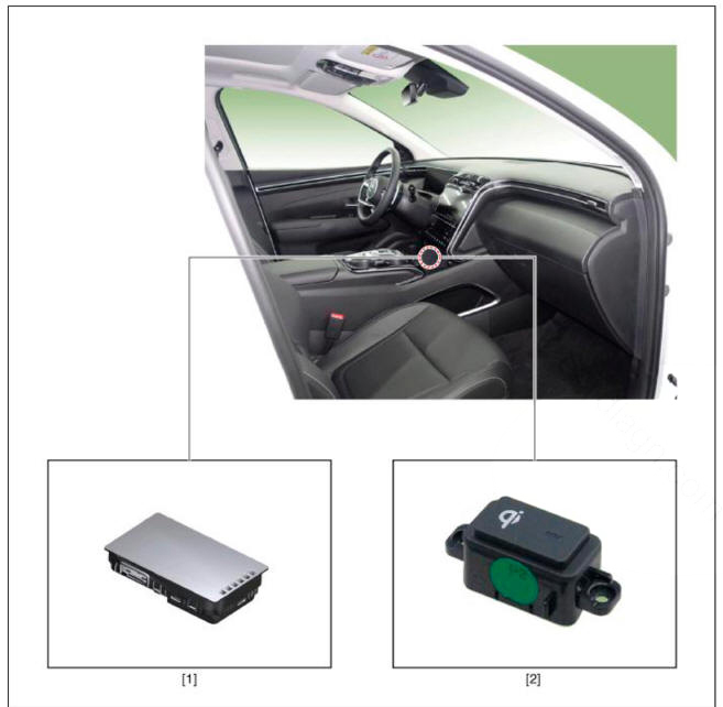
Components

- Wireless power charging unit
- Wireless power charging lamp
Troubleshooting
Wireless Power Charger System Troubleshooting

R-l. Check the wireless power charger system operation
- If the placement of a mobile phone is not detected
(1) If the internal temperature of the mobile phone battery is high, the mobile phone itself turns "OFF" the power.
WARNING
The temperature at which the power is automatically turned "OFF" differs by mobile phone model.
(2) If the mobile phone was placed outside the charging range
(3) If the mobile phone was placed by its LCD side on the charging pad surface (if the phone was placed upside down)
(4) If the mobile phone was turned 180º
- Check that the amber LED of the wireless charging lamp turns on when the mobile phone is in normal condition and is correctly placed.
R-2. Check for overcurrent, overheating and foreign matter
- Overcurrent: Charging stops in overcurrent of over 4.5 A
(1) The overcurrent error status will be reset when the current falls under 4.5 A or when ACC is turned off and on.
- Overheating : The unit will be automatically turned "OFF" when the internal temperature of the wireless charging unit is over 158ºF (70ºC).
(1) The error status will be reset when the internal temperature of the wirelss charging unit falls under 149ºF (65ºC).
- Foreign matter : When metallic objects such as coins, clips and precious metals are detected, charging will be stopped to prevent overheating.
(1) Error status will be reset when foreign matter is removed.
WARNING
- The amber LED of the charging display lamp blinks 10 times for 10 seconds, and then it is turned off for 50 seconds (total 60 seconds).
- The process is repeated for every 60 seconds.
- Turning ACC OFF/ON resets the error status and returns to normal operation.
Specification

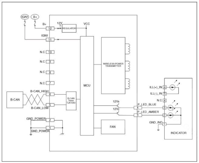
Circuit Diagram

Removal
WARNING
Handling wireless charging system parts by wet hands may cause electric shock.
- Disconnect the negative (-) battery terminal.
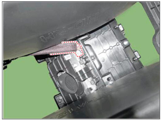
- Remove the floor console assembly.
(Refer to Body - "Floor Console Assembly")
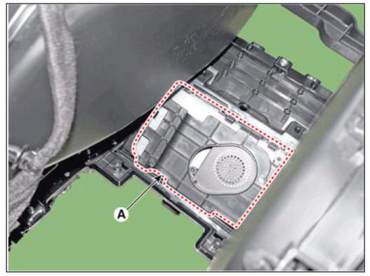
- Disconnect the wireless charging unit connector (A).

- Remove the wireless power charging unit (A).

Installation
- Install the wireless power charging unit.
- Connect the wireless power charging unit connector.
- Install the floor console assembly.
- Connect the negative (-) terminal
Inspesction
READ NEXT:
 Diagnosis With Diagnostic Tool
In the body electrical system, failure can be quickly diagnosed by using
the vehicle diagnostic system (diagnostic tool).
The diagnostic systemf diagnostic tool) provides the following information.
(1) Fault Code Searching : Checking fai
 Ignition Switch Assembly
Removal
Disconnect the negative (-) batteiy terminal.
Remove the steering column upper and lower shrouds.
(Refer to Body - "Steering Column Shroud Panel")
Remove the ignition switch (A) after disconnecting the 6P connector (B).
 Anti-theft System (UK only)
Components Location
UIP(Ultrasonic Intrusion Protection) Sensor
UIP(Ultrasonic Intrusion Protection) Siren
Description
Anti Theft Device
Block Diagram
This system is designed to provide protection from unauthorised entry into
th
SEE MORE:
 Idle Stop and Go (ISG)
Idle Stop and Go helps reduce fuel
consumption by automatically shutting
down the engine, when the vehicle is
at a standstill (i.e. red stop light, stop
sign, and traffic jam) subject to certain
prerequisite conditions being satisfied as
listed
 Tire Rotation
Tire Wear
WARNING
Using tires and wheel other than the recommended sizes could cause
unusual handling characteristics
and poor vehicle control, resulting in a serious accident.
Measure the tread depth of the tires.
Tread depth limit : 1.6
Information
- Home
- Hyundai Tucson - Fourth generation (NX4) - (2020-2023) - Owner's Manual
- Hyundai Tucson - Fourth generation (NX4) - (2020-2023) - Workshop Manual