Hyundai Tucson: Starting System- Description
The starting system includes the battery, starter, solenoid switch, ignition switch, ignition lock switch, connection wires and the battery cable.
When the ignition key is turned to the start position, current flows and energizes the starter motor's solenoid coil.
The solenoid plunger and clutch shift lever are activated, and the clutch pinion engages the ring gear.
The contacts close and the starter motor cranks.
In order to prevent damage caused by excessive rotation of the starter armature when the engine starts, the clutch pinion gear overruns.
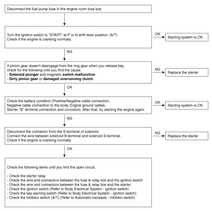
Troubleshooting
WARNING
The battery must be in good condition and fully charged for this troubleshooting

Starting system- Description
The starting system includes the battery, starter, solenoid switch, ignition switch, ignition lock switch, connection wires and the battery cable.
When the ignition key is turned to the start position, current flows and energizes the starter motor's solenoid coil.
The solenoid plunger and clutch shift lever are activated, and the clutch pinion engages the ring gear.
The contacts close and the starter motor cranks.
In order to prevent damage caused by excessive rotation of the starter armature when the engine starts, the clutch pinion gear overruns.
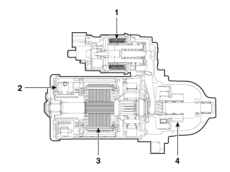
- Solenoid
- Brush assembly
- Armature
- Overrun clutch
Specification
Starter

Circuit Diagram

READ NEXT:
 Engine Mechanical System - Removal
Removal
Turn the ignition switch OFF and disconnect the battery (-) terminal.
Remove the air cleaner assembly.
(Refer to Engine Mechanical System - "Air Cleaner")
Remove the engine room under cover.
(Refer to Engine Mechanic
Engine Mechanical System - Installation
Installation
Install in the reverse order of removal.
Disassembly
Remove the M-terminal nut (A) on the magnetic switch assembly (B).
After loosening the screws (A), remove the magnetic switch assembly.
Remove the throug
Free Running Inspection
Place the starter motor in a vise equipped with soft jaws and connect a
fully-charged 12-volt battery to
starter motor as follows.
Connect a test ammeter (150-ampere scale) and carbon pile rheostats
shown is the illustration.
Connect a
SEE MORE:
Seat Belt Pretensioner
Description
The Seat Belt Pretensioners (BPT) are installed inside Center Pillar (LH & RH).
When a vehicle
crashes with a certain degree of frontal impact, the pretensioner seat belt
helps to reduce the severity of
injury to the front seat
Repair procedures
Compession Pressure Inspection
WARNING
If the there is lack of power, excessive oil consumption or poor
fuel economy, measure the compression
pressure.
Start the engine and turn the coolant temperature to 80 - 95 ºC and stop.
Remove the e
Information
- Home
- Hyundai Tucson - Fourth generation (NX4) - (2020-2023) - Owner's Manual
- Hyundai Tucson - Fourth generation (NX4) - (2020-2023) - Workshop Manual
