Hyundai Tucson: Smart Key System - Inspection
Self Diagnosis With Scan Tool
It will be able to diagnose defects of SMART KEY system with diagnostic tool quickly, diagnostic tool can operates actuator forcefully, input/output value monitoring and self diagnosis.
The following three features will be major problem in SMART KEY system.
- Problem in SMART KEY unit input.
- Problem in SMART KEY unit.
- Problem in SMART KEY unit output.
So the following three diagnosis operates will be the major problem solution process.
- SMART KEY unit Input problem : switch diagnosis
- SMART KEY unit problem : communication diagnosis
- SMART KEY unit Output problem : antenna and switch output diagnosis
Switch Diagnosis
- In the body electrical system, failure can be quickly diagnosed by using
the vehicle diagnostic system (diagnostic tool).
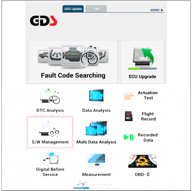
The diagnostic systemf diagnostic tool) provides the following information.
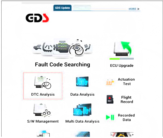
(1) Fault Code Searching : Checking failure and code number (DTC)
(2) Data Analysis : Checking the system input/output data state
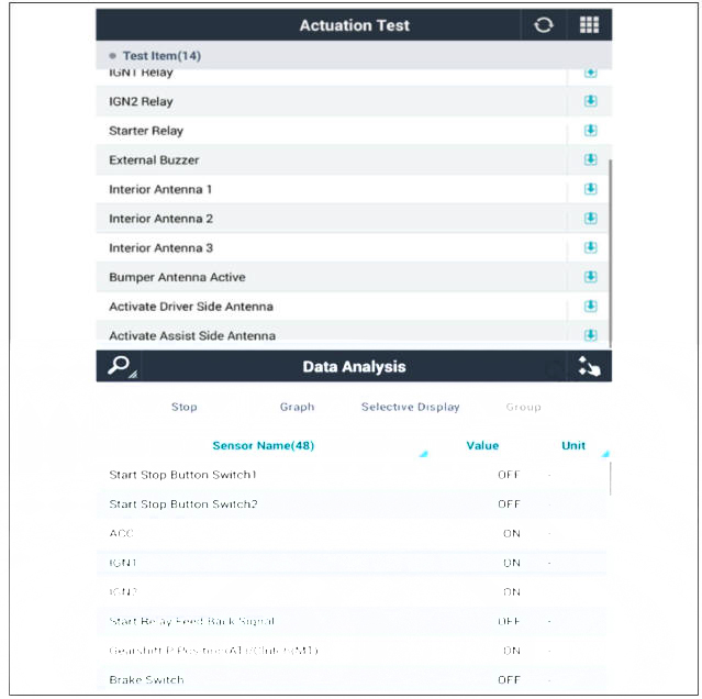
(3) Actuation test: Checking the system operation condition
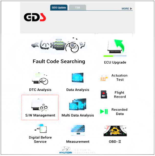
(4) S/W Management: Controlling other features including system option setting and zero point adjustment
- If diagnose the vehicle by diagnostic tool, select "DTC Analysis" and "Vehicle".
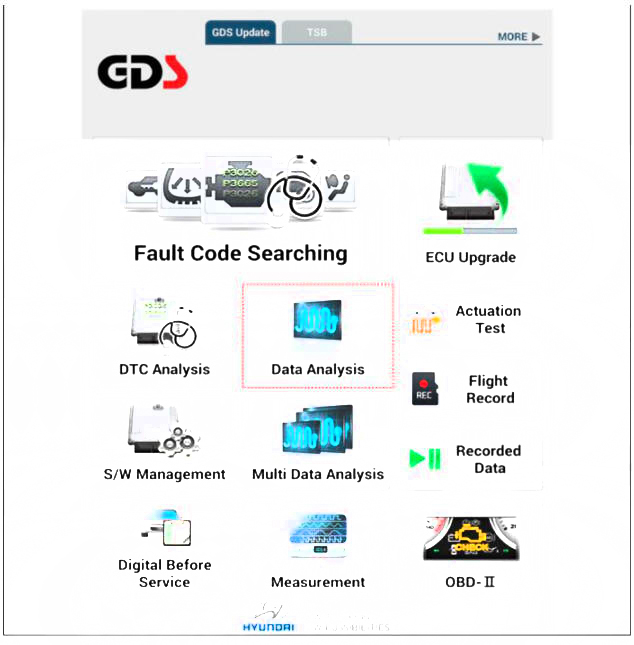
- If check current status, select the "Data Analysis" and "Car model".
- Select the SMK' to be checked in order to check the vehicle with the tester.
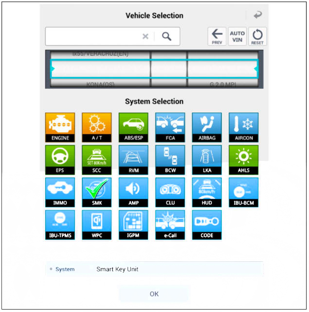
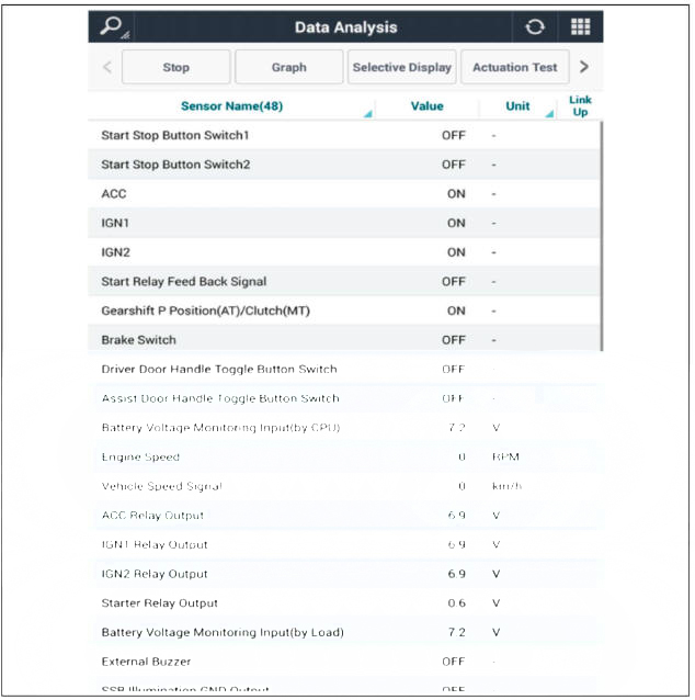
- You can see the situation of each switch on scanner after connecting the "current data" process.

Fault Code Searching
- Fault code searching that the each linked components operates normal.
- Connect the cable of diagnostic tool to the data link connector in driver side crash pad lower panel.
- Select the Fault Code Searching' and 'Car model'.

Antenna Actuation Diagnosis
- Connect the cable of diagnostic tool to the data link connector in driver side crash pad lower panel.
- Select the 'Actuation Test' and 'Car model'.

- Set the smart key near the related antenna and operate it with a diagnostic tool.
- Set the smart key near the related antenna and operate it with a diagnostic tool.
- If the LED of smart key is blinking, the smart key is normal.
- If the LED of smart key is not blinking, check the voltage of smart key battery.
- Antenna actuation
- Interior Antenna 1
- Interior Antenna 2
- Bumper Antenna
- Driver Door Antenna
- Assist Door Antenna
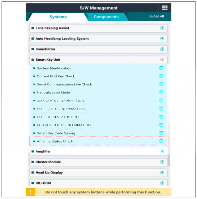
Antenna Status Check
- Connect the cable of diagnostic tool to the data link connector in driver side crash pad lower panel.
- Select the 'S/W Management' and 'Car model'.
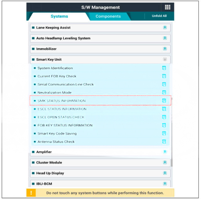
- Select the 'Smart Key Unit' and 'Antenna Stams Check'.
- Set the smart key near the related antenna and operate it with a diagnostic tool.
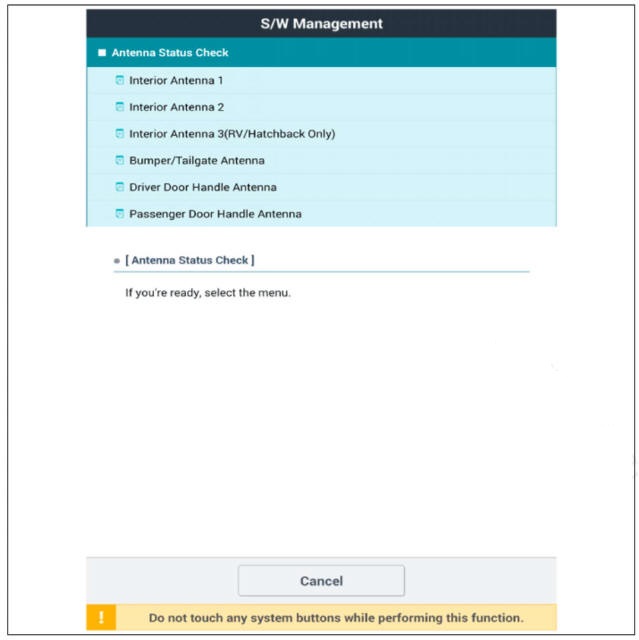
- If the smart key runs normal, the related antenna, smart key(transmission, reception) and exterior receiver are normal.
- Antenna status
- Interior Antenna 1
- Interior Antenna 2
- Bumper Antenna
- Driver Door Antenna
- Assist Door Antenna
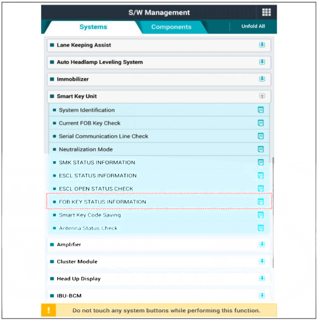
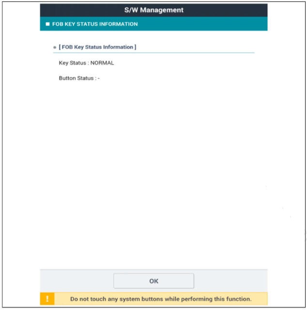
FOB Status Check
- Connect the cable of diagnostic tool to the data link connector in driver side crash pad lower panel.
- Select the 'S/W Management' and 'Car model'.

- Select the 'Smart Key Unit' and 'FOB KEY STATUS IMFORMATION'.
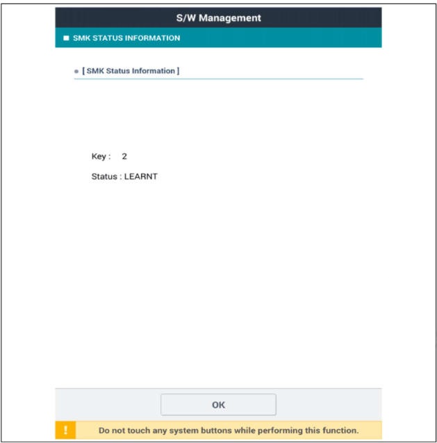
Smart Key Status Check
- Connect the cable of diagnostic tool to the data link connector in driver side crash pad lower panel.
- Select the 'S/W Management' and 'Car model'.
- Select the 'Smart Key Unit' and 'SMK STATUS INFORMATION'.
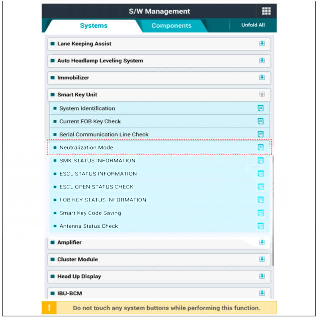
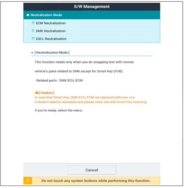
Neutralization Stams Check
- Connect the cable of diagnostic tool to the data link connector in driver side crash pad lower panel.
- Select the 'S/W Management' and 'Car model'.

- Select the 'Smart Key Unit' and 'Neutralization Mode'.
READ NEXT:
 Smart Key Code Saving
Smart
Connect the DLC cable of diagnostic tool to the data link connector (16
pins) in driver side crash pad lower panel, turn the
power on diagnostic tool.
Select the 'S/W Management' and 'Car model'.
Select the
Interior Antenna
Interior 1 Antenna
Take care not to scratch the crash pad and related parts.
Disconnect the negative (-) battery terminal.
Remove the ecall unit.
(Refer to Emergency Call system - "Emergency Call (eCall) Unit")
Remove the inter
Exterior Bumper Antenna
Disconnect the negative (-) battery terminal.
Lift the vehicle.
Disconnect the antenna connector (A) from the rear bumper.
Remove the antenna (B) after loosening mounting nuts.
Buzzer
Disconnect the negative (-) battery terminal.
SEE MORE:
Cooling Fan Assembly
Components
Cooling fan
Fan motor
Cooling fan shroud
Cooling Fan Assembly
Disconnect the negative battery terminal.
Remove the radiator.
(Refer to Cooling System - "Radiator")
Remove the cooling fan (A) from the rad
Remote control switch
Components
Remote control switch (Audio swtich)
Remote control switch (Cruise control switch)
Circuit
Diagram
Trip+SCC+MSLA+LFA
Inspection
Check for resistance between terminals in right switch position.
Trip/Cruise
Information
- Home
- Hyundai Tucson - Fourth generation (NX4) - (2020-2023) - Owner's Manual
- Hyundai Tucson - Fourth generation (NX4) - (2020-2023) - Workshop Manual
