Hyundai Tucson: Power Door Locks
Front Door Lock Module Inspection
Inspection
- Remove the front door trim.
(Refer to Body - "Front Door Trim")
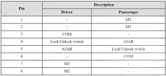
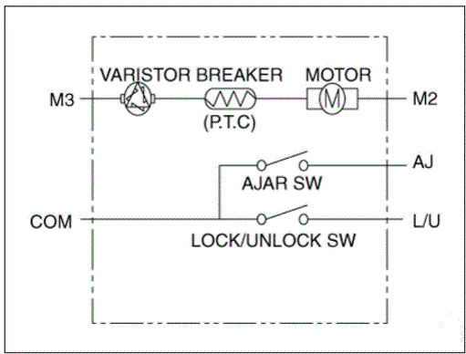
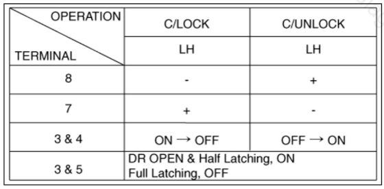
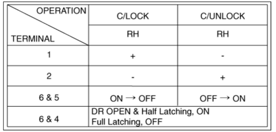
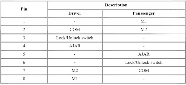
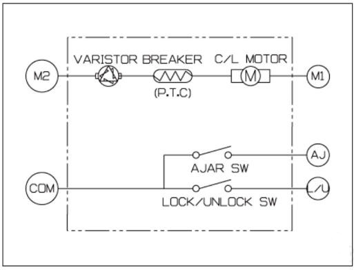
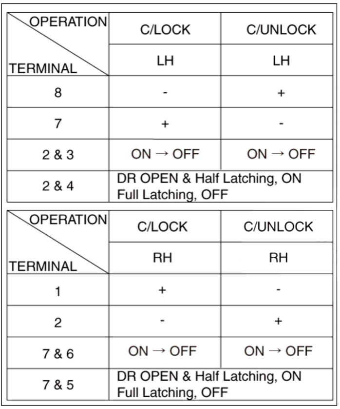
- Disconnect the connectors from the actuator.
- Check actuator operation by connecting power and ground according to the table.
Rear Door Lock Module Inspection
- Remove the rear door trim.
(Refer to Body - "Rear Door Trim")
- Disconnect the connectors from the actuator.
- Check actuator operation by connecting power and ground according to the table.
Tailgate Lock Module Inspection
- Remove the tailgate trim.
(Refer to Body - "Tail Gate Trim")
- Disconnect the connector from the actuator
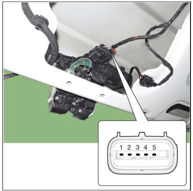
- Check actuator operation by connecting power and ground according to the table.
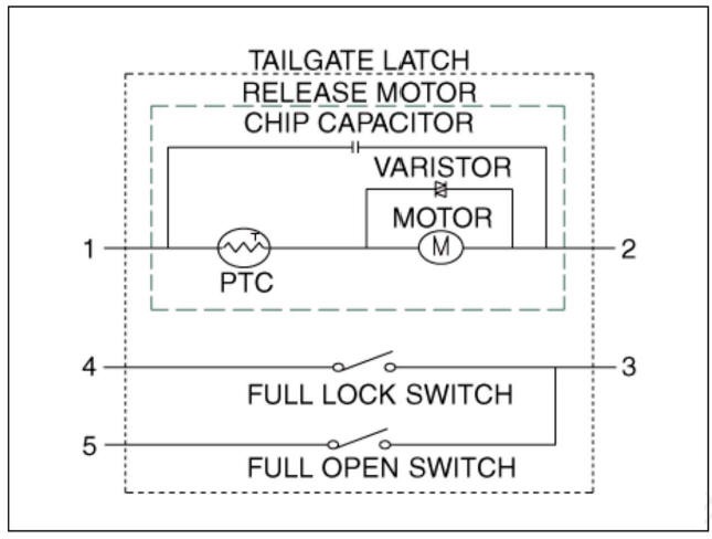
Hood Switch
- Disconnect the hood switch connector (A).
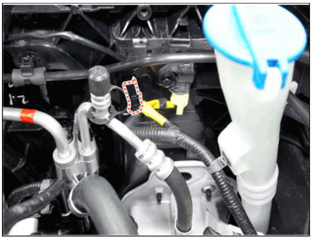
- Check for continuity between the terminals and ground according to the circuit diagram.

Inspection
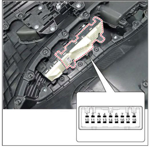
Power Door Lock Switch Inspection
1.1. Check for continuity between the terminals. If there is an abnormality, replace the switch.
Diagnosis with Diagnostic Tool
- In the body electrical system, failure can be quickly diagnosed by using
the vehicle diagnostic system.
The diagnostic system provides the following information.
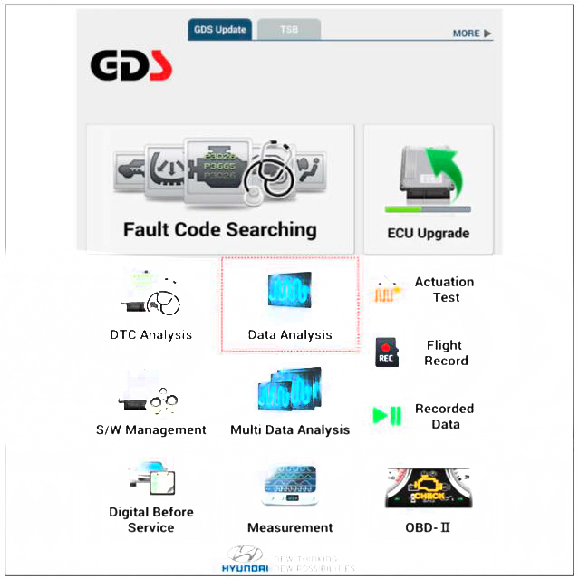
(1) Fault Code Searching : Checking failure and code number (DTC)
(2) Data Analysis : Checking the system input/output data state
(3) Actuation test: Checking the system operation condition
(4) S/W Management: Controlling other features including system option setting and zero point adjustment
- If diagnose the vehicle by diagnostic tool, select "DTC Analysis" and "Vehicle".
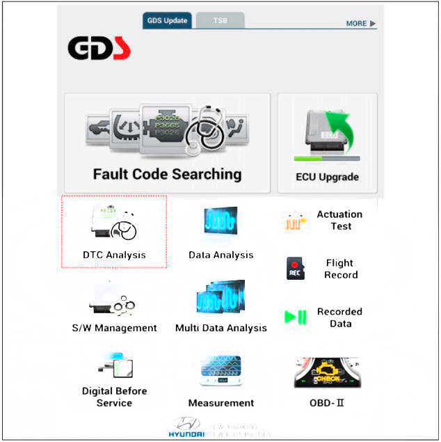
- If check current status, select the "Data Analysis" and "Car model".
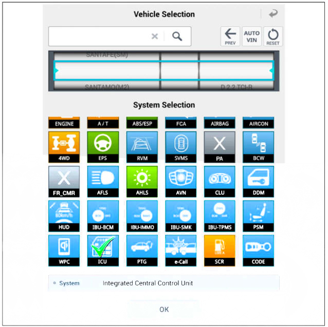
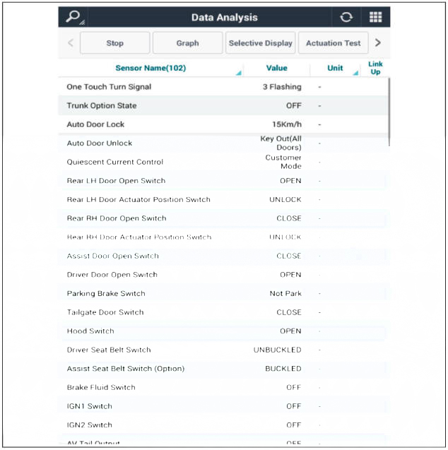
- Select the 'ICU' to search the current state of the input/output data.
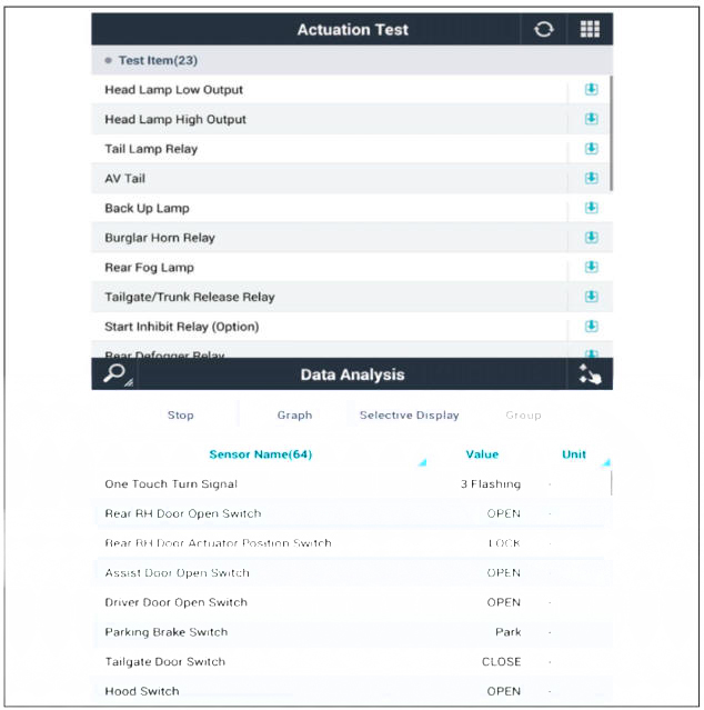
- To forcibly actuate the input value of the module to be checked, select option 'Actuation Test'.
Removal
Driver Power Door Lock Switch
- Disconnect the negative (-) battery terminal.
- Remove the front door trim.
(Refer to Body - "Front Door Trim")
- Remove the power window switch assembly (A).
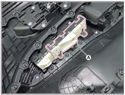
Installation
Driver Power Door Lock Switch
- Install the power door lock swtich assembly.
- Install the front door trim.
READ NEXT:
 Function Of Safety Power Window
Operation
When driver door power window auto-up switch is operated, safety function is
activated.
Safety function condition
When detect the force of 100N (using the lON/mm spring) during the window
rising, window is
reversed.
Length
 Initializing Method of the Safety Power Window
Initializing of Battery Connection
When the battery power is removed for over 5 minutes, safety power window
switch need the
initializing.
(1) Power window operation before initializing
Manual-Up/Down function is available
Auto-Up fun
SEE MORE:
 Engine And Transaxle Assembly - Removal and Installation
Remove the engine cover (A).
Installation is reverse order of removal
Removal and
Installation
Front Under Cover
Remove the engine room under cover (A).
Tightening torque :
7.8 - 11.8 N.m (0.8 - 1.2 kgf.m, 5.8 - 8.7 lb-ft)
 Height adjust
Component Location
Height adjust
Replacement
Remove the front seat belt upper anchor.
(Refer to Front Seat Belt - "Front Seat Belt Pretensioner")
After loosening the mounting bolts, then remove the height adjust (A).
T
Information
- Home
- Hyundai Tucson - Fourth generation (NX4) - (2020-2023) - Owner's Manual
- Hyundai Tucson - Fourth generation (NX4) - (2020-2023) - Workshop Manual