Hyundai Tucson: Charging System - Cleaning
- Make sure that the ignition switch and all accessories are in the OFF position.
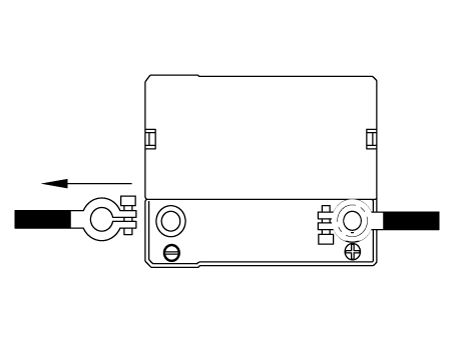
- Disconnect the battery cables (negative first).
- Remove the battery from the vehicle.
WARNING
Care should be taken in the event the battery case is cracked or leaking, to protect your skin from the electrolyte.
Heavy rubber gloves (not the household type) should be wore when removing the battery.

- Inspect the battery tray for damage caused by the loss of electrolyte. If acid damage is present, it will be necessary to clean the area with a solution of clean warm water and baking soda. Scrub the area with a stiff brush and wipe off with a cloth moistened with baking soda and water.
- Clean the top of the battery with the same solution as described above.
- Inspect the battery case and cover for cracks. If cracks are present, the battery must be replaced.
- Clean the battery posts with a suitable battery post tool.
- Clean the inside surface of the terminal clamps with a suitable battery cleaning tool. Replace damaged or frayed cables and broken terminal clamps.
- Install the battery in the vehicle.
- Connect the cable terminals to the battery post, making sure tops of the terminals are flush with the tops of the posts .
- Tighten the terminal nuts securely.
- Coat all connections with light mineral grease after tightening.
WARNING
When batteries are being charged, an explosive gas forms beneath the cover of each cell. Do not smoke near batteries being charged or which have recently been charged. Do not break live circuit at the terminals of batteries being charged.
A spark will occur when the circuit is broken. Keep open flames away from battery.
Description
Vehicles have many control units that use more electricity. These units control their own system based on information from various sensors. It is important to provide a stable power supply as these sensors bring diverse information. Battery sensor is mounted on battery (-) terminal. It transmits battery voltage, current, temperature information to ECM. ECM controls generating voltage by duty cycle based on these signals.

Removal
- Turn the ignition switch OFF and disconnect the battery (-) terminal.
- Remove the battery.
(Refer to Charging System - "Battery")
- Disconnect the battery sensor connector (A).

- Remove the battery sensor (A).
Tightening torque : 26.5 - 32.4 N.m (2.7 - 3.3 kgf.m, 19.5 - 23.9 Ib-ft)

Installation
- Install in the reverse order of removal.
WARNING
For the vehicle equipped with a battery sensor, be careful not to damage the battery sensor when the battery is replaced or recharged.
1) When replacing the battery, the new battery should be of the same type, capacity and brand with the previous one. If a battery of a different type is replaced, the battery sensor may recognize the battery to be abnormal.
2) When installing the ground cable on the negative post of battery, tighten the clamp to the specified torque. An excessive tightening can damage the PCB internal circuit and the battery terminal.
3) When recharging the battery, ground the negative terminal of the booster battery to the vehicle body.
Adjustment
Battery Sensor Recalibration Procedure
After reconnecting the battery negative cable, AMS function does not operate until the system is stabilized, for about 4 hours. If disconnecting the negative (-) battery cable from the battery during repair work for the vehicle equipped with AMS function, Battery sensor recalibration procedure should be performed after finishing the repair work.
- Turn the Iginition switch ON and OFF.
- Park the vehicle for about 4 hours with the hood and all doors closed.
READ NEXT:
 Ignition System - Description
The ignition coil is a kind of small transformer that transforms the battery
voltage to 30 kV or more to
create a spark in the spark plug gap in the cylinder.
The igniter embedded in the ignition coil includes the power transistor and it
is a
 On-vehicle- Inspection
Inspect ignition coil assembly and Perform spark test
Check for DTCs.
WARNING
If a DTC is present, perform troubleshooting in accordance with the
procedure for that DTC.
(Refer to DTC guide)
Check if sparks occur.
Without diagnost
SEE MORE:
 Controller
Component
Connector Pin Function
Replacement
Disconnect the negative (-) battery terminal.
Remove the front monitor.
(Refer to Body Electrical System - "Front Monitor")
Remove the heater & AJC control unit (A).
 Transfer Assembly- Removal
Removal
A Type
Remove the engine room under cover.
(Refer to Engine Mechanical System - "Engine Room Under Cover")
Remove the front driveshaft assembly. Right side
(Refer to Driveshaft and Axle - "Front Driveshaft")
Information
- Home
- Hyundai Tucson - Fourth generation (NX4) - (2020-2023) - Owner's Manual
- Hyundai Tucson - Fourth generation (NX4) - (2020-2023) - Workshop Manual