Hyundai Tucson: Rear wheel speed sensor - Inspection
Hyundai Tucson - Fourth generation (NX4) - (2020-2023) - Workshop Manual / Brake System / ESC (Electronic Stability Control) System / Rear wheel speed sensor - Inspection
Inspection
- Measure the output voltage between the terminal of the wheel speed sensor and the body ground.
WARNING
In order to protect the wheel speed sensor, when measuring output voltage, a 100Q resister must be used as shown.
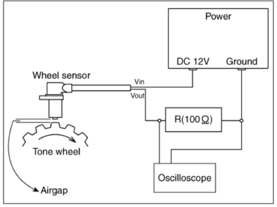
- Compare the change of the output voltage of the wheel speed sensor to the normal change of the output voltage as shown below.
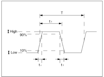
- I low : 5.95 ~ 8.05 mA
- I High : 11.9-16.1 mA
- Frequency range : 0.03 ~ 3000 HZ
Installation
- Install in the reverse order of removal.
Description
The DBC function is the acronym word of Downhill Brake Control function. When a vehicle goes down the hill, just pushing the DBC switch enables the car to keep its vehicle's speed at a constant value without operating the brake pedal. The DBC function is operatjed when the vehicle is on the decline and its velocity is under the predetermined speed.
Removal
- Disconnect the battery negative ( - ) terminal.
- Remove the floor console upper cover.
(Refer to Body - "Floor Console Assembly")
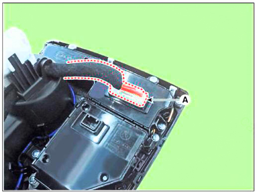
- Disconnect the floor console upper cover switch connector (A).
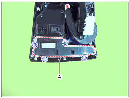
- Remove the screws and remove the floor console upper cover switch (A).

Installation
- Install in the reverse order of removal.
READ NEXT:
 Introduction of Quick Brake Warning System (ESS)
Description
In case of quick brake by driver, the brake lamp or turn signal is blinked to
warn against the vehicle at rear.
Basic function (Blinking the brake lamp/emergency lamp)
Operation condition : In case of quick brake or opera
General Information
Troubleshooting
Specifications
Tightening Torque
Special Service Tools
SEE MORE:
Hood
Adjustment
After loosening the hinge (A) mounting bolt, adjust the hood (B) by
moving it up and down or from side to side and tighten
the bolt.
Adjust the hood height by moving the hood overslam bumpers (C) up and
down.
After loosenin
Windshield Glass - Replacement
Components
Windshield glass
Windshield glass upper molding
Replacement
WARNING
Put on gloves to prevent hand injuries.
WARNING
Use seat covers to avoid damaging any surfaces.
Remove the front pillar trim.
(Refer to Interior Tri
Information
- Home
- Hyundai Tucson - Fourth generation (NX4) - (2020-2023) - Owner's Manual
- Hyundai Tucson - Fourth generation (NX4) - (2020-2023) - Workshop Manual
