Hyundai Tucson: Power Tailgate Module - Component Location
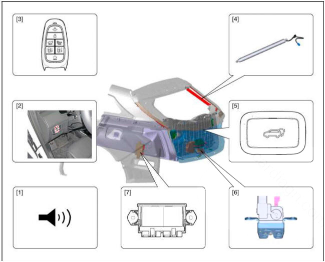
- Buzzer
- Tailgate open switch (Crsah pad lower switch)
- Fob key
- Spindle Drive (2EA)
- Tailgate inner switch
- Power Latch
- PTG Control Module
Tailgate Inner Switch
Failure Inspection
Diagnosis with diagnostic tool
- In the body electrical system, failure can be quickly diagnosed by using
the vehicle diagnostic system (diagnostic tool).
The diagnostic system (diagnostic tool) provides the following information.
(1) Fault Code Searching : Checking failure and code number (DTC)
(2) Data Analysis : Checking the system input/output data state
(3) Actuation test: Checking the system operation condition
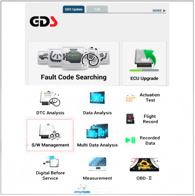
(4) S/W Management: Controlling other features including system option setting and zero point adjustment
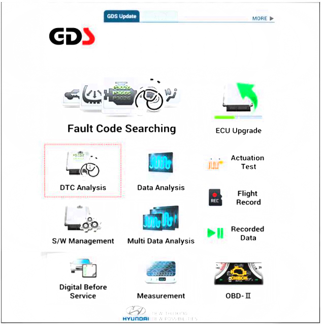
- If diagnose the vehicle by diagnostic tool, select "DTC Analysis" and "Vehicle".
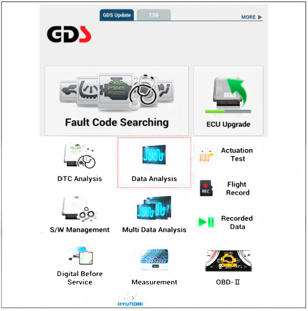
- Select the 'Data Analysis'.
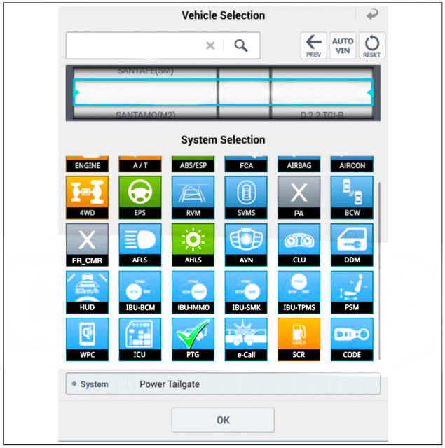
- Select the 'PTG' to search the current state of the input/output data.
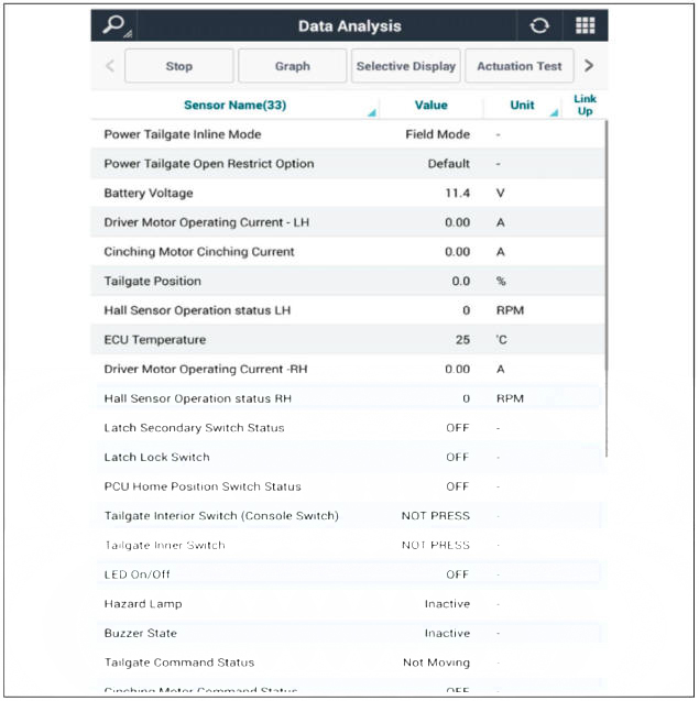
Mode Change (Power Tailgate System)
- After replacing with a new power tailgate module, check for DTC code at
all times.
If DTC code B24B0 exists, perform power tailgate mode change.
- After connecting the diagnostic tool. Select the 'S/W Management' and 'Car model'.
- Select the "Power Tailgate" and Power Tailgate Mode Configuration" procedure.
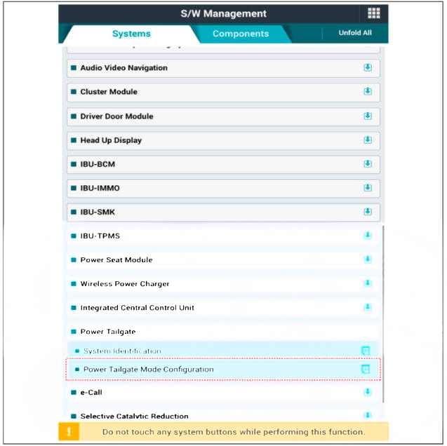
- Perform the "Power Tailgate Mode Configuration" procedure according to the diagnostic tool screen message.
System Initialization
System initialization is needed to recognize the closing position of the tailgate to power tailgate module.
The initialization process after battery power reset, system initialization is needed to recognize the maximum opening and closing tailgate position exactly.
The power tailgate operates normally after system initialization is completed.
Procedure :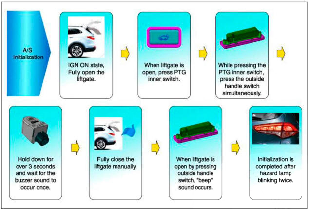
Inspection and Test - Power Tailgate System
Power Tailgate system is a complex system that consists of several components. To get an accurate test result, the control module of the Power Tailgate must be inspected.
The most trustworthy, effective and accurate method is using diagnostic tool required by power tailgate.
diagnostic tool helps technicians when inspecting a disabled switch, and enables to check the current status record of the switch ofPower Tailgate control module.
The battery must be fully charged before conducting all of the test on power tailgate, and all of the interfering elements of the system must be shown and understood, (refer to the explanation of smart tailgate) Refer to the analysis reference table when inspecting and testing the smart tailgate.
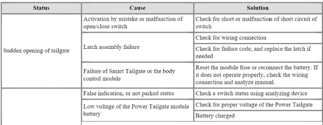
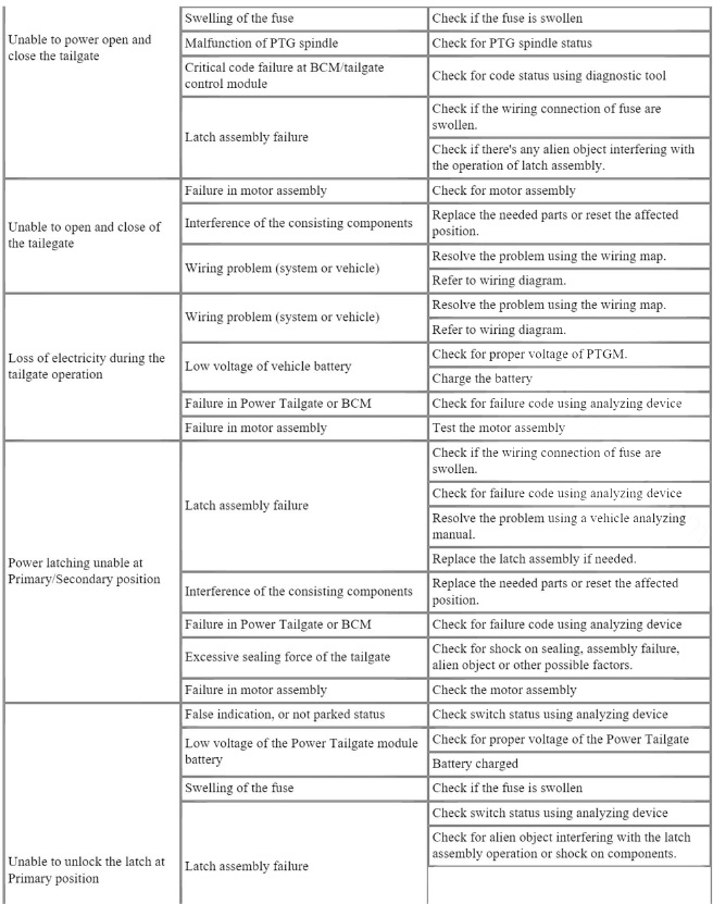
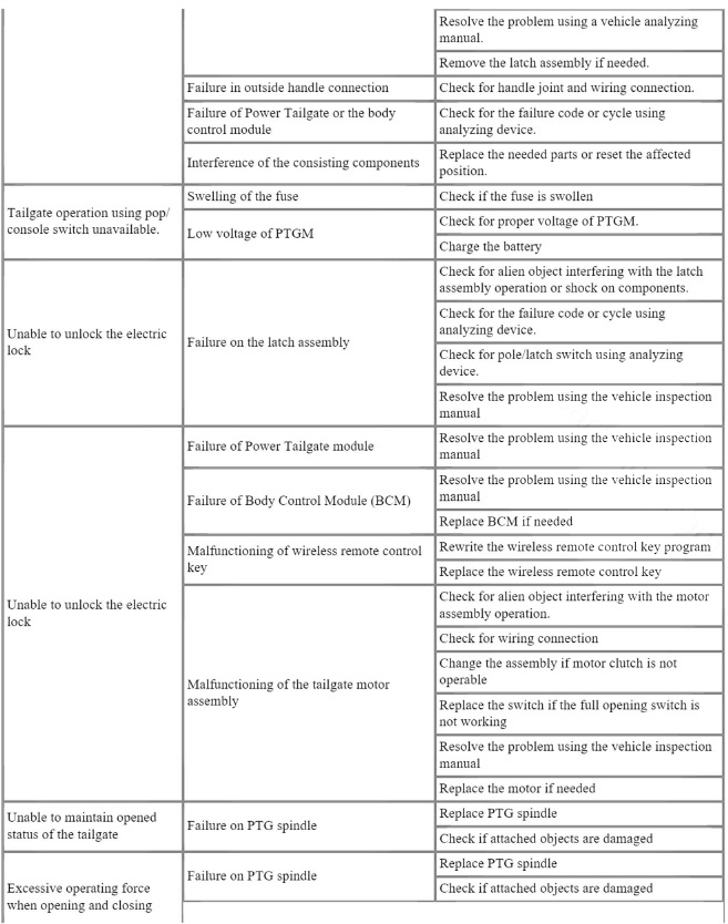
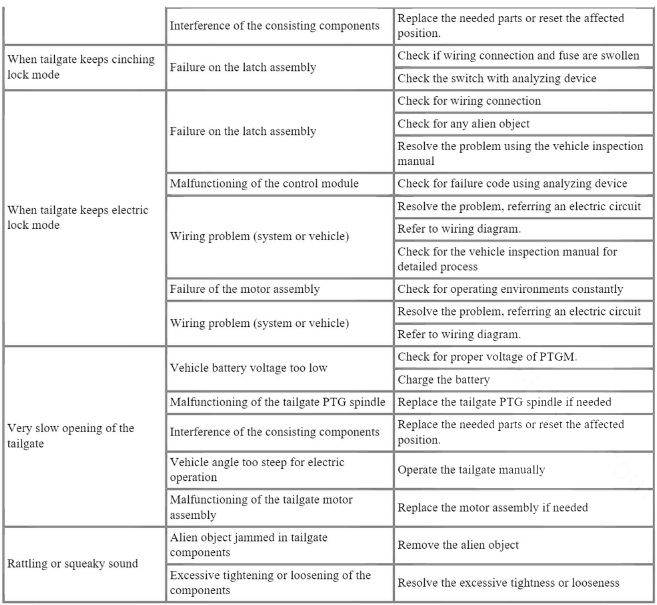
Circuit Diagram
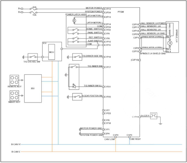
Removal
1) After replacing with a new power tailgate module, check for DTC code at all times.
If DTC code B24B0 exists, perform power tailgate mode change.
(Refer to Power Tailgate Module - "Troubleshooting")
2) After replacing with a new power tailgate module, perform the system initialization.
(Refer to Power Tailgate Module - "Troubleshooting")
3)Before delivery to customer, operate the power tailgate to be sure that there is no warning sound.
- Disconnect the negative (-) battery terminal.
- Remove the luggage side trim LH.
(Refer to Body - "Luggage Side Trim")
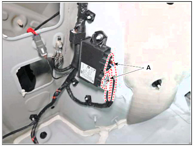
- Disconnect power tailgate unit connectors (A).
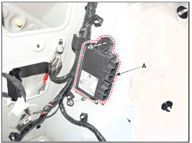
- Remove the power tailgate unit (A) after loosening mounting nuts.
Installation
- Install the power tailgate unit.
- Install the luggage side trim LH.
- Connect the negative (-) battery terminal.
Inspection
Inspection of the Power Tailgate System
Refer to Power Tailgate System - "Troubleshooting"
Removal
- Disconnect the negative (-) battery terminal.
- Remove the tailgate trim.
(Refer to Body - "Tail Gate Trim")
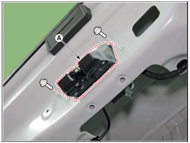
- Disconnect the latch connector (A).
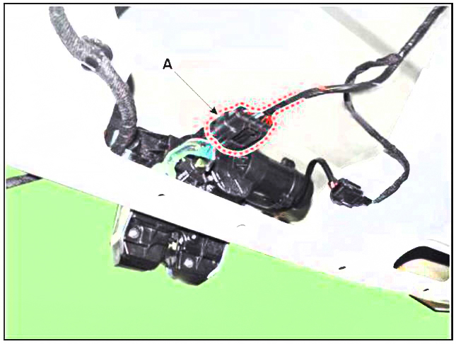
- Remove the power tailgate latch (A) after loosening mounting bolts.
Installation
- Install the power tailgate latch.
- Install the tailgate trim.
- Connect the negative (-) battery terminal.
Inspection
Inspection of the Power Tailgate Latch
Refer to Power Tailgate System - "Troubleshooting"
Removal
- Disconnect the negative (-) battery terminal.
- Remove the tailgate trim.
(Refer to Body - "Tail Gate Trim")
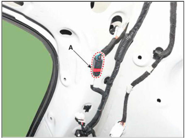
- Disconnect the PTG spindle connector (A).
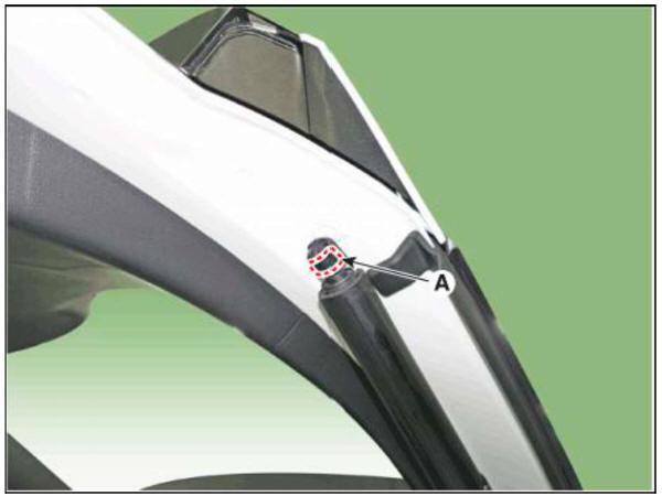
- Using a flat-tip screwdriver, remove the mounting clip (A).
- Remove the spindle assembly after loosening mounting bolts.
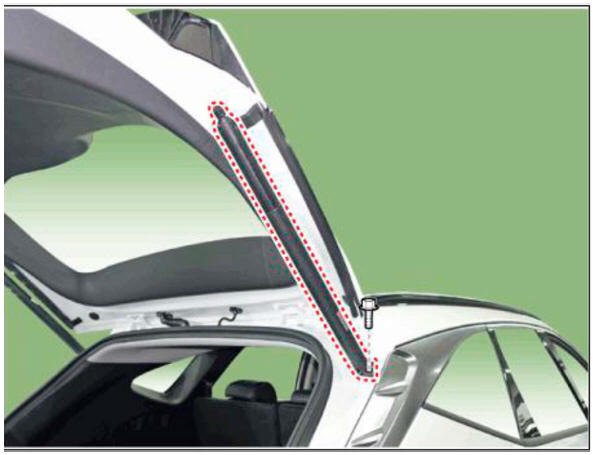
- Take care not to be closed the tail gate, when removing the lift.
Installation
- Install the PTG spindle assembly.
Tightening torque : 6.9 - 10.8 Nm (0.7 -1.1 kgf.m, 5.0 - 7.9 lbf.ft)
- Connect the PTG spindle connector.
- Install the luggage side trim.
- Connect the negative (-) battery terminal.
READ NEXT:
 Windshield Wiper Washer
Component Location
Windshield wiper arm & blade
Wiper & washer switch
Windshield washer hose & nozzle
Windshield wiper motor & linkage
Washer motor
Washer reservoir
Front wiper relay (Engine room junction block)
 Inspection (With diagnostic tool)
In the body electrical system, failure can be quickly diagnosed by using
the vehicle diagnostic system (diagnostic tool).
The diagnostic system (diagnostic tool) provides the following information.
(1) Fault Code Searching : Checking failu
 Windshield Wiper Washer - Removal
Disconnect the negative (-) battery terminal.
If necessary, release the wiper blade fixing clip(A) by pulling up and
remove the wiper blade(B) from the inside radius of
wiper arm.
Remove the cowl top cover.
(Refer to Body - &quo
SEE MORE:
 Trailer towing equipment
Hitches
Information
The mounting hole for hitches are located
on both sides of the underbody behind the
rear tires.
It's important to have the correct hitch
equipment. Crosswinds, large trucks
going by, and rough roads are a few
reasons why
 Door Outside Handle
When removing with a flat-tip screwdriver or remover, wrap protective
tape around the tools to
prevent damage to components.
Put on gloves to prevent hand injuries.
Remove the door outside handle cover (A)
Remove the plug ho
Information
- Home
- Hyundai Tucson - Fourth generation (NX4) - (2020-2023) - Owner's Manual
- Hyundai Tucson - Fourth generation (NX4) - (2020-2023) - Workshop Manual