Hyundai Tucson: Panorama Sunroof
Component Location
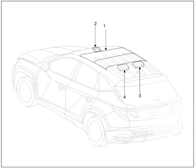
- Panorama sunroof
- Panorama sunroof switch
- Panorama sunroof motor & Controller
- Roller blind motor & Slave controller
Circuit Diagram
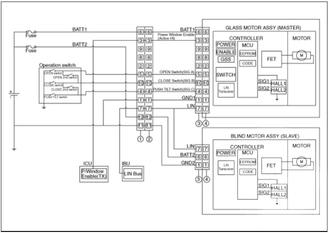
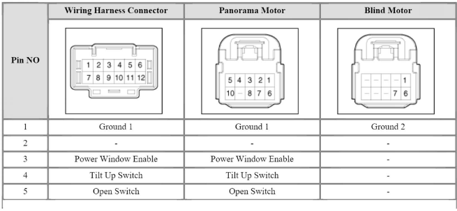
Connector Pin Information

Removal
- Disconnect the negative (-) battery terminal.
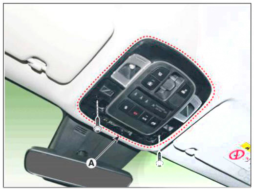
- Remove the overhead console cover (A).
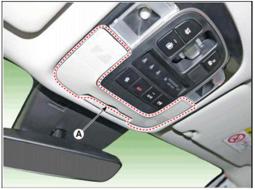
- Remove the mounting screws.and then remove the overhead console (A).
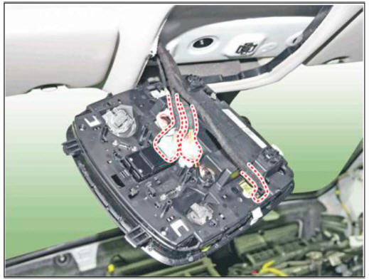
- Remove the overhead console after disconnect the connector (A).
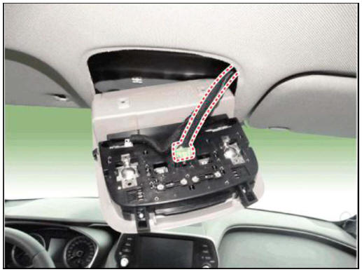
- Remove the overhead console lamp assembly then check for continuity between terminals. If the continuity is not as specified, replace the map lamp switch.
Installation
- Install the overhead console lamp after connecting the connector.
- Connect the negative (-) battery terminal.
Replacement
- Disconnect the negative (-) battery terminal.
- Remove the roof trim assembly.
(Refer to Body - "Roof Trim Assembly")
- Loosen the mounting bolts,disconnect the connector and remove the sunroof motor (A).
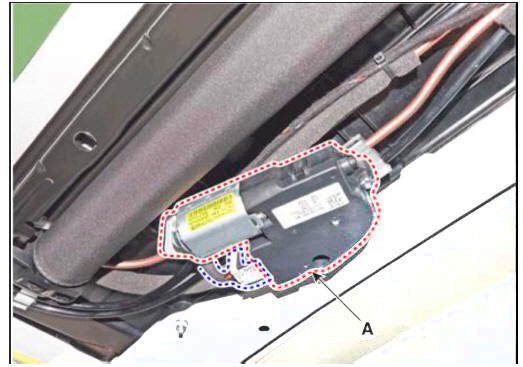 Glass Motor
- Loosen the mounting bolts,disconnect the connector and remove the blind motor (A).
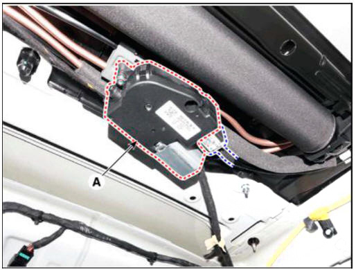 Roller Blind Motor
Adjustment
Resetting The Panoramaroof
Whenever the vehicle battery is disconnected or discharged, or you use the emergency handle to operate the panoramaroof, you have to reset your panoramaroof system as follows :
You need to reset the sunroof motor to its default settings for the following cases :
- The sunroof motor loses battery power temporarily because the batteiy or fuse is replaced or the batteiy has died.
- The automatic opening or closing of the sunroof, a one-touch feature, does not function properly.
- The sunroof reopens during automatic closing even if there is no object caught in the sunroof (safety feature)
- Turn the ignition key to the ON position and then close the panoramaroof completely.
- Release the panoramaroof control lever.
- Press and hold the CLOSE button for more than 10 seconds until the sunroof has moved slightly.
- Release the panoramaroof control lever.
- Press and hold the CLOSE button once again within 5 seconds until the panorama sunroof do as follows ;
- Blind open and glass open -> Glass close -> Blind close Then release the lever.
- Reset procedure of panorama system is finished.
Protecting The Overheated Motor
In order to protect the overheated panoramaroof motor by continuous motor operation, the panoramaroof ECU controls the Run-time and Cool-time of motor as followings;.
- The panoramaroof ECU detects the Run- time of motor
- Motor can be operated continuously for the 1st Run-time(120 +- lOsec.).
- Motor which is operated continuously stops operating after the 1st Run-time(120 +- lOsec.).
- And then Motor is not operated for the 1st Cool-time(18 +- 2sec.).
- Motor is operated for the 2nd Run-time(10 +- 2sec.) at the continued motor operation after 1st Cooltime( 18 +- 2sec.)
- Motor which is operated continuously stops operating after the 2nd Run-time(10 +- 2sec.)
- Motor is not operated for the 2nd Cool-time(18 +- 2sec.).
- Motor repeats the 2nd Run-time and 2nd Cool-time at the continued motor operation.
- I n case that motor is not operated continuously, the Run-time which is limited for protecting the overheated motor is increased.
- The Run-Time of motor is initialized to "0" if the batteiy or fuse is reconnected after being disconnected, discharged or blown.
T1 : 120 +- 10 sec., T2 : 18 +- 2 sec.
T3 : 10 +- 2 sec., T4 : 18 +- 2 sec
READ NEXT:
 Lighting System - Removal
Troubleshooting
Specifications
Removal
Disconnect the negative (-) battery terminal.
Remove the front bumper assembly.
(Refer to Body - "Front Bumper Assembly")
Disconnect the head lamp connector (A).
Loo
 Head Lamp Aiming
Instructions
Alternately turn the adjusting gear to adjust the head lamp aiming.
If beam-setting equipment is not available, proceed as follows:
Draw vertical lines (Vertical lines passing through respective head lamp
centers) and a horizo
SEE MORE:
 Vehicle break-in process
By following a few simple precautions for the first 600 miles (1,000km) you
may add to
the performance, economy and life of your vehicle.
Do not race the engine.
While driving, keep your engine speed (RPM, or revolutions per minute)
betwe
 Connector and Terminal Function
Connector Funtion
Removal
Disconnect the negative (-) battery terminal.
Remove the rear bumper assembly.
(Refer to Body - "Rear Bumper Assembly")
Disconnect the rear corner radar connector (A).
Loosen the mounting n
Information
- Home
- Hyundai Tucson - Fourth generation (NX4) - (2020-2023) - Owner's Manual
- Hyundai Tucson - Fourth generation (NX4) - (2020-2023) - Workshop Manual