Hyundai Tucson: Immobilizer System - Removal
Hyundai Tucson - Fourth generation (NX4) - (2020-2023) - Workshop Manual / Body Electrical System / Immobilizer System / Immobilizer System - Removal
Removal
- Disconnect the negative (-) battery terminal.
- Remove the heater control unit.
(Refer to Heating,Ventilation And Air Conditioning - "Heater Control Unit")
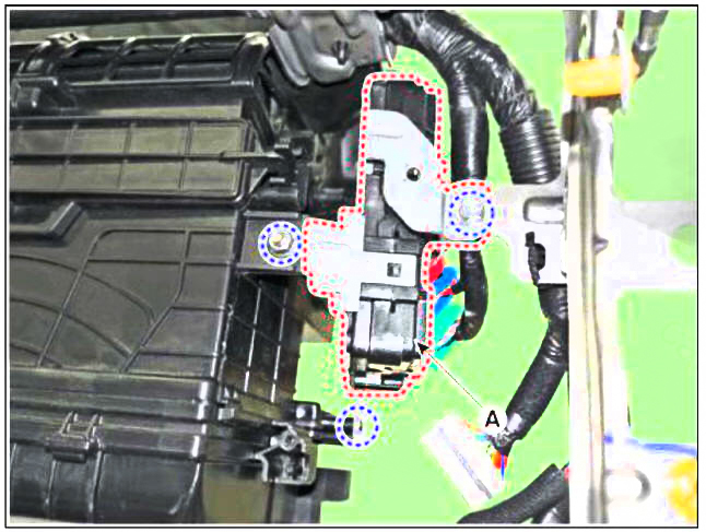
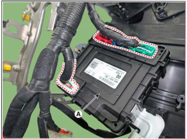
- Loosen the mounting bolt,nut,screw and remove the Integrated Body Control Unit (A).

- Disconnect the connectors and remove the Integrated Body Control Unit (A).

Installation
- Install the Integrated Body Control Unit.
- Install the heater control unit.
- Connect the negative (-) terminal
Removal
- Disconnect the negative (-) battery terminal.
- Remove the crash pad lower panel.
(Refer to Body - "Crash Pad Lower Panel")
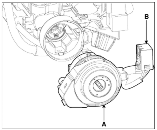
- Disconnect the 6P connector (B) of the coil antenna and then remove the coil antenna (A) after loosening the screw.

Installation
- Install the coil antenna and connect the 6P connector.
- Install the crash pad lower panel.
- Connect the negative (-) battery terminal.
READ NEXT:
 Auto Lighting Control System
Description
It's a system that uses illumination sensor to automatically turn ON the tail
lamp and head lamp based
on the change in surrounding environment's illumination condition. It activates
when the vehicle enters/
exits tunnel, o
 Auto Head Lamp Leveling Device
Component Location
Head lamp leveling actuator (Inside head lamps)
Head lamp leveling switch
Removal
Disconnect the negative (-) battery terminal.
Remove the crash pad lower panel.
(Refer to Body - "Crash Pad Lower Panel&q
 Button Engine Start System
Description
The System offers the following features :
Changing the state of engine ignition and power by using the start
button.
Controlling external relays for ACC / IGN1 / IGN2 terminal switching and
STARTER, without use of mechanical
SEE MORE:
 Lighting
Exterior lights
Lighting control
To operate the lights, turn the knob at
the end of the control lever to one of the
following positions:
OFF position
AUTO headlamp position
Position lamp position
Headlamp position
Daytime Running
 Integrated Thermal Management Module (ITM)
Components
Integrated thermal management module (ITM)
Heater pipe
Heater hose
Turbo charger coolant hose
Heater pipe A
Heater pipe A gasket
Oil cooler hose A
Oil cooler pipe
Integrated Thermal Management Module (ITM)
WARNING
Information
- Home
- Hyundai Tucson - Fourth generation (NX4) - (2020-2023) - Owner's Manual
- Hyundai Tucson - Fourth generation (NX4) - (2020-2023) - Workshop Manual