Hyundai Tucson: Gear acmator assembly- Description
- Components location : DCT (Dual Clutch Transmission)

Function
The input shaft speed sensor is important in that it detects the input shaft RPM and sends this information to the Transmission Control Module (TCM).
It provides important input information for electric control.
The information is needed in all operations, including feedback control, gear shift control and failure detection of other sensors.
Components
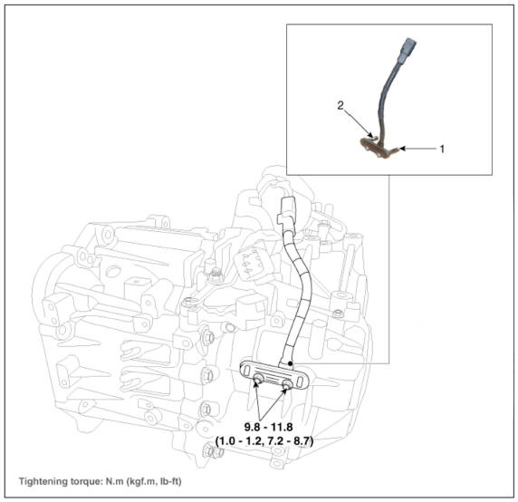
- Input shaft speed sensor 1 (Odd)
- Input shaft speed sensor 2 (Even)
Specification

Circuit Diagram

Inspection
- The DCT system can be more quickly diagnosed for troubles by using the vehicle diagnostic system (diagnostic tool). (Refer to DTC guide) diagnostic tool provides the following information.
1) Self diagnosis : Inspects and displays diagnostic trouble code (DTC)
2) Sensor data : Checks the system input/output value staftis
3)Forced operation : Checks the system operating status
4) Additional function : Controls system options, zero point adjustment and other functions
Removal
- Turn ignition switch OFF and disconnect the battery negative (-) terminal.
- Remove the air cleaner assembly and air duct.
(Refer to Engine Mechanical System - "Air cleaner")
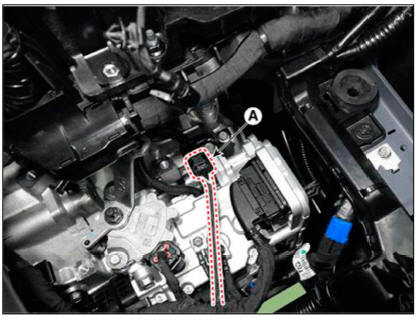
- Disconnect the input shaft speed sensor connector (A).
- Remove the clutch actuator.
(Refer to Dual Clutch Transmission Control System - "Clutch Actuator & TCM Assembly")
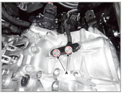
- Remove the input shaft speed sensor (A).
Tightening torque : 9.8 - 11.8 N.m (1.0 - 1.2kgf.m, 7.2 - 8.7 lb-ft)

Installation
- Install in the reverse order of removal.
WARNING
Before installing the input speed sensor,check the assembled state
of the O-rings (A) and should
apply gear oil to the surface of O- rings.

Description
- The inhibitor switch is installed on top of transmission, and is connected to the shift lever through shift cable.
- Inhibitor switch signals (SI, S2, S3, S4) are transmitted to the TCM according to the driver's shift lever control.

READ NEXT:
 Inhibitor switch/ Manual control lever
Components
Inhibitor switch
Manual control lever
Fault Diagnosis
Fault Diagnosis for Symptom
Specifications
Signal Code Table
Inspection
WARNING
Thoroughly check connectors for looseness, poor connection, bending,
cor
Inhibitor switch/ Manual control lever- Removal
Turn ignition switch OFF and disconnect the batteiy negative (-)
terminal.
Make sure vehicle does not roll before setting shift lever to "N"
position.
Remove the air cleaner assembly and air duct.
(Refer to Engine Mechanical
Shift lever knob & boots assembly
Components
Shift lever knob & boots assembly
Shift lever assembly
Shift cable
Manual control lever
Shift cable retainer
Removal
Remove the shift lever knob & boots (A) pull both of it up.
Remove the floor consol
SEE MORE:
Paddle shifter (Manual shift mode)
The paddle shifter is available when
the shift lever/button is in the D (Drive)
position or the manual shift mode.
With the shift lever/button in the D
position
The paddle shifter will operate when the
vehicle speed is more than 6mph.
Pu
Driveshaft side oil seal #3 B Typel
Remove the transfer assembly.
(Refer to 4 Wheel Drive (4WD) System - "Front Wheel Transfer Assembly")
Remove the dust cover (A).
Remove the oil seal #2 (A).
Remove the oil seal #3 (A).
Install the oil
Information
- Home
- Hyundai Tucson - Fourth generation (NX4) - (2020-2023) - Owner's Manual
- Hyundai Tucson - Fourth generation (NX4) - (2020-2023) - Workshop Manual
