Hyundai Tucson: Driveshaft Assembly- Installation
Installation
- To install, reverse the removal procedures.
- Check the alignment.
(Refer to Suspension System - "Alingment")
Removal
- Remove the front drive shaft.
(Refer to Driveshaft Assembly - "Front Driveshaft")
- Remove the trans axle side joint.
(Refer to Driveshaft Assembly - "Transaxle Joint")
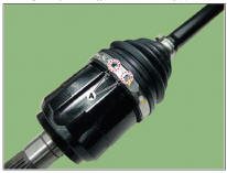
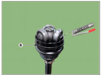
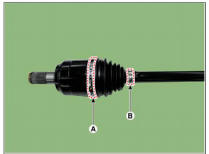
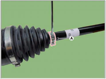
- Remove the dynamic damper band (A, B) using driver (-).
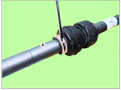

WARNING
When removing the dynamic damper, lubricate the shaft with soapy water to prevent shaft damage.
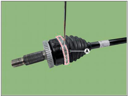
- Remove the dynamic damper (A).

Installation
- Install the dynamic damper (A).

WARNING
When installing the dynamic damper, install it in set with the mounting part (A) of the shaft.
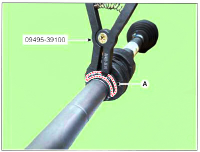
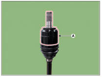
- Install the dynamic damper band (A) using SST (09495-39100).
- Install the transaxle side joint.
(Refer to Driveshaft Assembly - "Transaxle Joint")
- Install the front driveshaft.
(Refer to Driveshaft Assembly - "Front Driveshaft")
Removal
WARNING
- Drive shaft joints require special grease, so do not add any other type of grease.
- When replacing the boot band, it must be a new one.
- Remove the front drive shaft.
(Refer to Driveshaft Assembly - "Front Driveshaft")
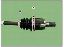
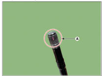
- Remove the transaxle side large diameter (A) and small diameter (B) boot
bands.
WARNING
Use the right tool for each type of boot band as shown in the table
below . 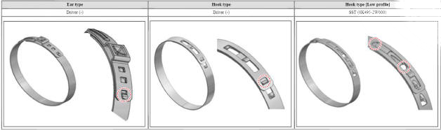

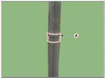
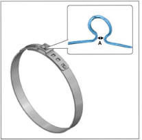
WARNING
When using the low profile hook type boot band, fit the SST tip (B)
into the boot band hole (A) as shown below.
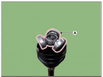
- Remove the trans axle joint housing (A).

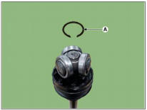
- Remove the snap ring (A) using a snap ring pliers.

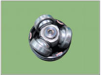
- Remove the spider assembly (A) irom the drive shaft using a puller.

- Remove trans axle side boot (A).

- Clean the inside of the spider assembly and joint housing.
WARNING
Remove grease inside the housing as much as possible.
Inspection
- Check spline (A) for damage wear crack.
- Check the boot for w'ater or foreign objects.
- Check joint assembly for damage wear crack and rust.
- Replace any defective parts.
Installation
WARNING
- When assembling, be careful not to let dust and foreign substances enter.
- Driveshaft joints require special grease, so do not add any other type of grease.
- Boot bands must use the new: one.
- Install the transaxle side boot (A) and boot band (B) on the driveshaft.
WARNING
Put the boot band (B) first on the drive shaft before installing the
boot (A). 
WARNING
When installing the boot, seats in the mounting part (A).
- Install the spider assembly (A) on the shaft (B), then press it using a
mallet.
WARNING
- When installing the spider assembly (A), install it in the correct direction.
- Installing in the wrong direction can cause secondary
quality problems.

- When installing the spider assembly, install it according to
the boot shape.
- Install the snap ring (A) using the snap ring pliers.
WARNING
- When replacing the joint assembly, use the new one provided in the joint kit.
- The snap ring must be new.
- After installing the snap ring, make sure that there are only 2
- 3 splines in position (A).

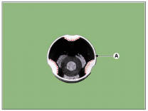
- Apply specified grease inside the joint housing (A) and boot (B).
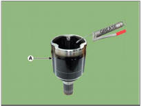
WARNING
- Use the grease provided with the joint boot kit.
- Apply about 10% grease to the housing (A) and about 30% grease to the boot (B).
- Driveshaft joints require special grease, so do not add any other type of grease.
- Install the trans axle side joint housing (A).
WARNING
- When installing the housing, turn the boot to fit each other.
- If the shape of housing and boot does not fit, there is a
possibility of leakage due to the gap. Be very careful.
- Adjust the air inside the boot to normal as shown below.
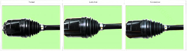
WARNING
After installing the jomt housing, perform air bleeding by pressing it several times until no air is heard.
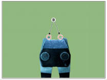
- Install the transaxle side joint large diameter (A) and small diameter
(B) boot band.

WARNING
- Install in the following order: large diameter boot band → small diameter boot band.
- Installing in the wrong order can cause leaks.
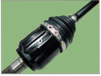
- When installing the ear type boot band, check the clearance (A) as shown below.
Clearance (A): 2.0 mm or less.
- When using the low profile hook type boot band, fit the SST tip
(B) into the boot band hole (A) as shown below.
- Install the front driveshaft.
(Refer to Driveshaft Assembly - "Front Driveshaft")
Removal
The type can replace the wheel side joint boot
- Remove the front drive shaft.
(Refer to Driveshaft Assembly - "Front Driveshaft")
- Remove the trans axle side joint.
(Refer to Driveshaft Assembly - "Transaxle Joint")
- Remove the dynamic damper.
(Refer to Driveshaft Assembly - "Dynamic Damper")
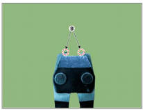
- Remove the wheel side joint small diameter (A) and large diameter (B) boot band using driver (-).
- Remove the wheel side joint boot (A).

WARNING
- Do not remove the wheel side joint housing (A).
- Reinstall the wheel side joint housing (A) may cause leakage,
so replace it with the shaft (B) as an
assembly.
The type can not replace the wheel side joint boot
- Remove the front drive shaft.
(Refer to Driveshaft Assembly - "Front Driveshaft")
- Remove the trans axle side joint.
(Refer to Driveshaft Assembly - "Transaxle Joint")
- Remove the dynamic damper.
(Refer to Driveshaft Assembly - "Dynamic Damper")
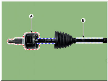
- Replace the wheel side joint assembly (A) and shaft (B).

WARNING
The wheel side joint boot can not be replaced, so replace the wheel side joint assembly (A) and shaft (B) together as an assembly.
READ NEXT:
 Driveshaft Assembly- Inspection
Check the boot for water or foreign objects.
Replace any defective parts.
Installation
The type can replace the wheel side joint boot
WARNING
When assembling, be careful not to let dust and foreign
substances enter.
Driveshaft join
Rear Axle Assembly- Removal- 2WD
Components
Rear brake disc
Rear hub assembly
Dust cover
Rear carrier assembly
Removal
2WD
WARNING
When lifting a vehicle using a lift, be careful not to damage the
lower parts of the vehicle (floor under cover,
fuel filter, fue
SEE MORE:
Air Cleaner Assembly
Removal and
Installation
Disconnect the battery negative terminal.
Disconnect the air flow sensor (AFS) connector (A).
Remove the air duct (A).
Disconnect the RCV hose (A).
Remove the air cleaner assembly
Tight
Integrated Thermal Management Module (ITM)
Description
Integrated Thermal Management Module (ITM) is a device that controls the
coolant flow rate according to coolant
temperature. At initial startup, the ITM quickly warms up the engine by
controlling the flow of the coolant and this fas
Information
- Home
- Hyundai Tucson - Fourth generation (NX4) - (2020-2023) - Owner's Manual
- Hyundai Tucson - Fourth generation (NX4) - (2020-2023) - Workshop Manual
