Hyundai Tucson: Body Control Module Controls The Followings
Description
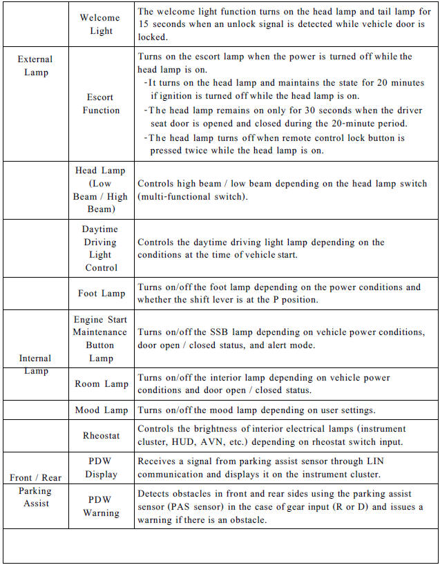
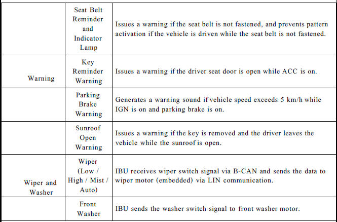
Body Control Module Controls The Followings
- Wiper & Washer Control
- Defroster Control
- Driving Control
- Tailgate Control
- Window Control
- Interior Control
- Exterior Control
- Panic alarm Control
- MTS
- Flasher output Control
- Door lock/unlock Control
- Burglar alarm Control
- Remote start Control
- UMS(User Mode Setting) Control
- Gateway/ Diagnosis
Integrated Body Control Unit (IBU)
Integrated body control unit has integrated several functions including body control module (IBU), smart key unit (SMK), and tire pressure monitoring system (TPMS).
- Body Control Module (IBU) Functions

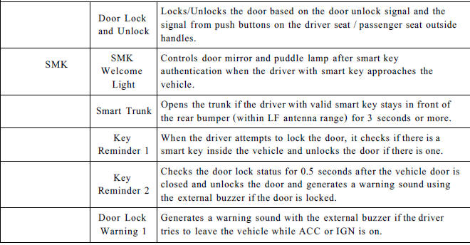
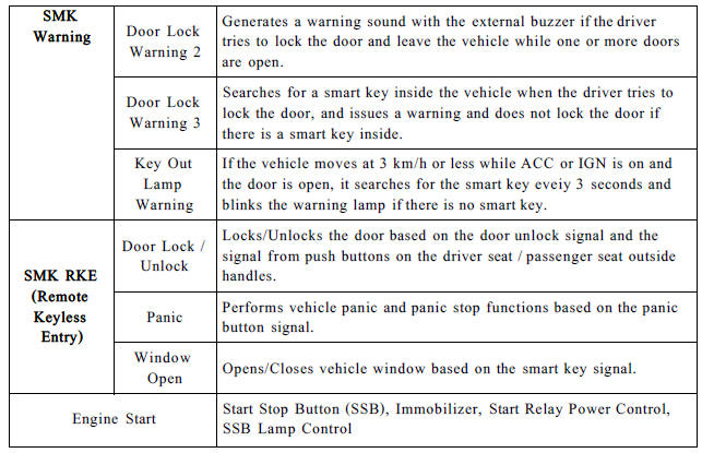
- Smart Key Unit (SMK) Functions
- Tire Pressure Monitoring System (TPMS) Functions
Tire pressure monitoring system continuously monitors pressure and temperature inside the tire in order to warn the driver of the changes in tire pressure that may have influence on vehicle driving conditions. TPMS control module analyzes the data from the WE (Wheel Electronic) sensor attached inside each wheel and determines the tire conditions and generates a signal that is necessary for warning lamp control.
Components
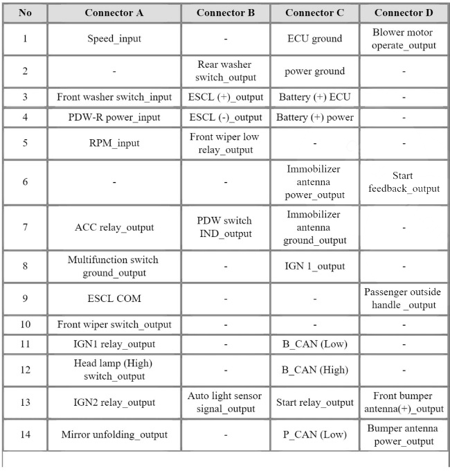
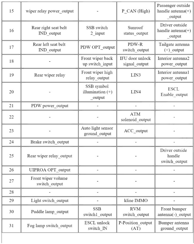
With Smart Key
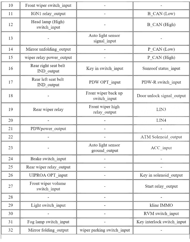
Connector Pin Information
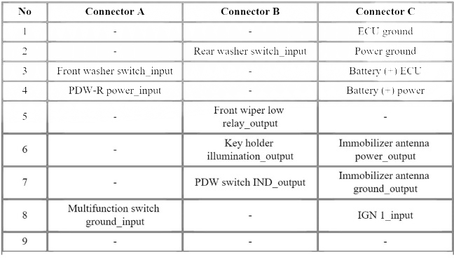
Without Smart Key
Connector Pin Information
Specifications
Removal
- Disconnect the negative (-) battery terminal.
- Remove the heater control unit.
(Refer to Heating, Ventilation And Air Conditioning - "Heater Control Unit")
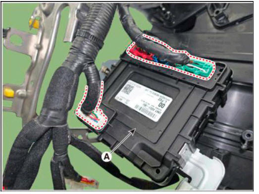
- Remove the IBU (A) after loosening mounting bolt, nut and screw.
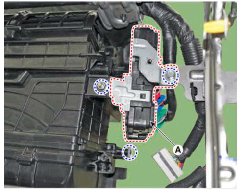
- Disconnect IBU connectors and then remove the IBU (A).
Installation
- Install the IBU and connect the connector.
- Install the heater control unit.
- Install the negative (-) battery terminal.
READ NEXT:
 IBU Diagnosis With Diagnostic Tool
In the body electrical system, failure can be quickly diagnosed by using
the vehicle diagnostic system.
(1) Fault Code Searching : Checking failure and code number (DTC)
(2) Data Analysis : Checking the system input/output data state
(3) A
IMS (Integrated Memory)
Description
The optimal seat position set by the driver is memorized into the power seat
unit by using IMS switch.
In case of the position change, the seat can restore its preset position by IMS
switch.
It has safety functions of restoring
Fuel Filler Door
Component Location
Fuel filler door release actuator
Inspection
Disconnect the negative (-) battery terminal.
Remove the fuel filler housing after opening the fuel filler door.
(Refer to Body - "Fuel Filler Door")
Dis
SEE MORE:
Console armrest
Component Location
Console armrest
Replacement
WARNING
When removing with a flat-tip screwdriver or remover, wrap
protective tape around the tools to
prevent damage to components.
Put on gloves to prevent hand injuries.
WARN
When Using the CVVD fixture/ When not using the CVVD fixture
When Using the CVVD fixture
(1) Install the CVVD fixture (A) over the CVVD assembly.
(2) Remove the CVVD assembly.
When not using the CVVD fixture
(3) Remove the CVVD assembly.
Remove the Intake CVVT (A).
Remove the
Information
- Home
- Hyundai Tucson - Fourth generation (NX4) - (2020-2023) - Owner's Manual
- Hyundai Tucson - Fourth generation (NX4) - (2020-2023) - Workshop Manual