Hyundai Tucson: BMS ECU Terminal and Input/Output Signal

Terminal Function
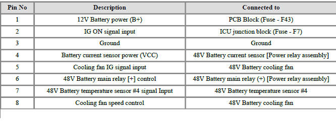
Connector B10-A

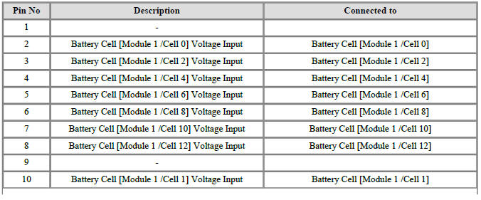
Connector B01-B

Removal
- Turn ignition switch OFF and disconnect the battery (-) terminal.
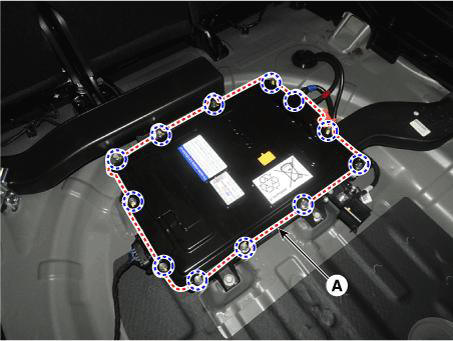
- Remove the 48V battery assembly.
(Refer to 48V Battery System - "Repair procedures")
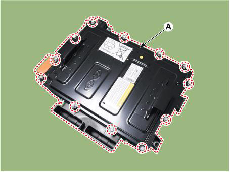
- Remove the battery cover (A) after loosening the mounting bolts.
Tightening torque : 7.8 - 11.8 N.m (0.8 - 1.2 kgf.m, 5.8 - 8.7 lb-ft)
- Remove the terminal capacitor (A) after loosening the mounting bolts.
Tightening torque : 7.8 - 11.8 N.m (0.8 - 1.2 kgf.m, 5.8 - 8.7 lb-ft)
- Remove the mounting nuts and remove the battery module (-) busbar (A).
Tightening torque : 7.8 - 11.8 N.m (0.8 - 1.2 kgf.m, 5.8 - 8.7 lb-ft)
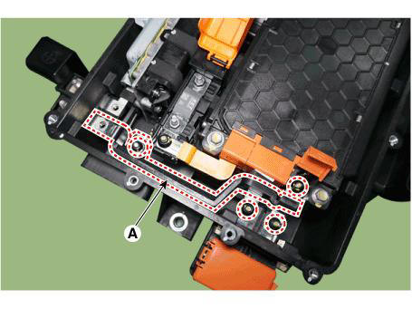
- Remove the mounting nuts and remove the battery module (+) busbar (A).
Tightening torque : 7.8 - 11.8 N.m (0.8 - 1.2 kgf.m, 5.8 - 8.7 lb-ft)
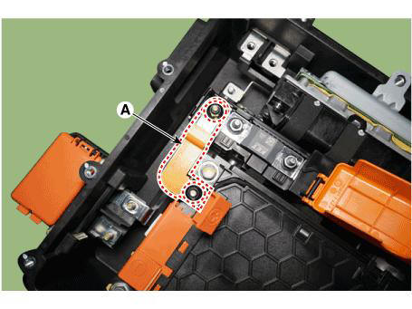
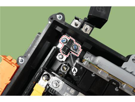
- Remove the BMS wiring harness terminal after loosening the mounting bolts (A).
Tightening torque : 7.8 - 11.8 N.m (0.8 - 1.2 kgf.m, 5.8 - 8.7 lb-ft)
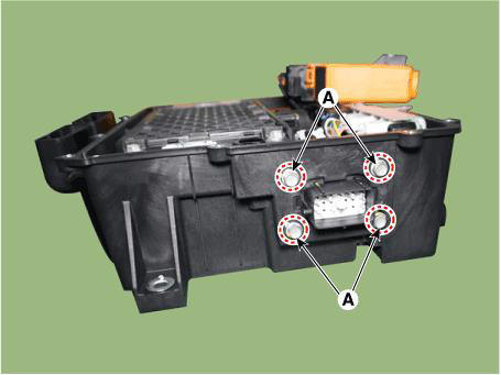
- Remove the 48V battery case assembly after loosening the mounting bolts (A).
Tightening torque : 7.8 - 11.8 N.m (0.8 - 1.2 kgf.m, 5.8 - 8.7 lb-ft)
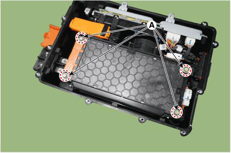
- Disconnect the BMS & LDC connectors (A).
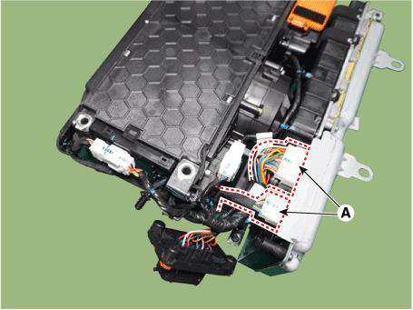
- Remove the BMS & LDC assembly.

Installation
- Install in the reverse order of removal.
Description
Mounted in the power relay assembly (RPA), the main fuse protects the high voltage battery and high voltage circuits from overcurrent.
Specifications

Removal
- Turn the ignition switch OFF and disconnect the battery (-) terminal.
- Remove the battery cover (A) after loosening the mounting bolts.
Tightening torque : 7.8 - 11.8 N.m (0.8 - 1.2 kgf.m, 5.8 - 8.7 lb-ft)
- Remove the mounting nuts and remove the main fuse (A).
Tightening torque : 7.5 - 10.5 N.m (0.76 - 1.07 kgf.m, 5.5 - 7.7 lb-ft)

Installation
- Install in the reverse order of removal.
Specifications

READ NEXT:
 Power Relay Assembly (PRA) - Removal
Removal
Remove the PRA assembly.
(Refer to 48V Battery System - "Power Relay Assembly (PRA)")
Remove the PRA cover.
Remove the mounting bolts and remove the power relay busbar (A).
Disconnect the main relay connector
Battery Pack Assembly Inlet Duct/ Battery Pack
Assembly Outlet Duct
Removal and
Installation
Battery Pack Assembly Inlet Duct
Turn the ignition switch OFF and disconnect the battery (-) terminal.
Remove the luggage board (A).
Separate the inlet cooling duct (A) in the direction of the arrow.
Tigh
Battery Module Inlet Duct
Turn ignition switch OFF and disconnect the battery (-) terminal.
Remove the 48V battery assembly
(Refer to 48V Battery System - "Repair procedures")
Remove the battery cover (A) after loosening the mounting bolts.
Tightening
SEE MORE:
Towing service
[A] : Dollies
If emergency towing is necessary,
we recommend having it done by
an authorized HYUNDAI dealer or a
commercial tow-truck service.
Proper lifting and towing procedures
are necessary to prevent damage to
the vehicle. The use o
Blower unit assembly
Components Location
Blower unit assembly
Components
Blower unit assembly
Intake actuator
Intake duct case LH
Intake seal
Intake door(l)
Intake door(2)
Intake duct case RH
Climate control actuator
PWM blower module
B
Information
- Home
- Hyundai Tucson - Fourth generation (NX4) - (2020-2023) - Owner's Manual
- Hyundai Tucson - Fourth generation (NX4) - (2020-2023) - Workshop Manual
